| InternalI2C | |
|
|

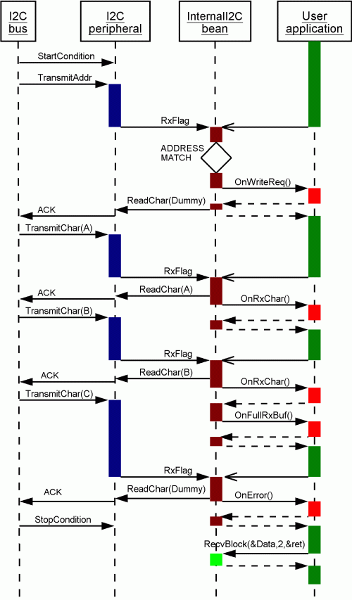
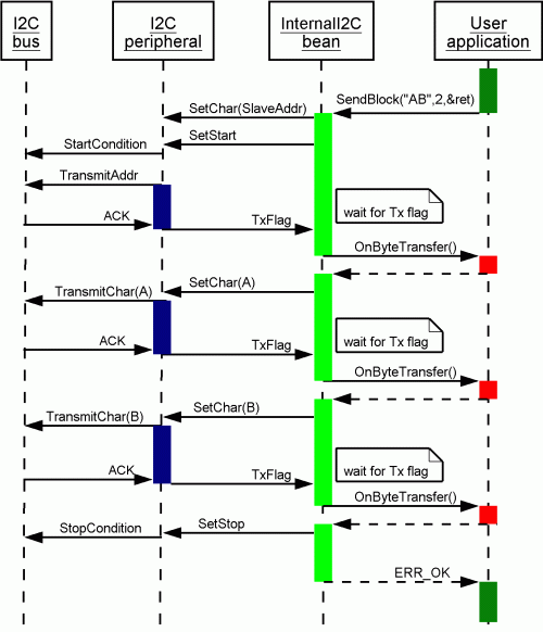
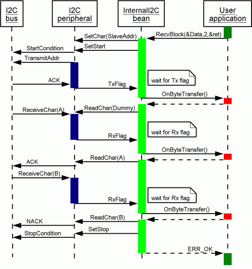
The examples are accompanied by sequence charts which demonstrate the sequence of calling the methods and events and internal processing of the communication. These charts show detailed information about InternalI2C component algorithm for a typical usage of this component. Each chart is composed of four objects. The first I2C bus object represents communication line that carries the information to other I2C node(s). The second I2C peripheral object represents the functions of the internal I2C peripheral module of the CPU. The third InternalI2C object represents generated InternalI2C component code (interrupt routines, methods). The fourth User application object represents a user written code. The third and the fourth objects are processed by CPU core, thus they cannot be performed concurrently and the control flow of the CPU core is divided into these objects.
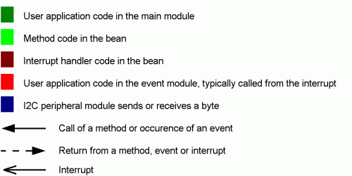
The colors and types of arrows used in diagrams mean:
 |
Typical settings and usage of InternalI2C component
- (1) Sending data in the MASTER mode
- (2) Receiving data in the MASTER mode
- (3) Sending data in the SLAVE mode
- (4) Receiving data in the SLAVE mode
- (5) Sending data in the MASTER mode without interrupts
- (6) Receiving data in the MASTER mode without interrupts
- (7) Slave Selection and general call in the MASTER mode.
- (8) Communication with external serial EEPROM memory.
(1) Sending data in the MASTER mode
Required component name is "I2C1"
and the following component settings: Mode selection - MASTER, Interrupt service - enabled.
OnTransmitData event is called at the end of data transmission. SelectSlave method is used for slave address selection and
SendBlock method is used for data sending start.
The example demonstrates sending of 2 bytes to the slave.
MAIN.C

byte flags;
byte err;
byte Data[]="AB";
word ret;
#define SLAVE 0x08

void main(void)
{

  /* Set slave address */
  (void)I2C1_SelectSlave(SLAVE);

  /* Clear "Complete" flag */
  flags = 0;

  /* Send bytes in master mode */
  err=I2C1_SendBlock(&Data,2,&ret);
  if(err!=ERR_OK) {
    /* Handle an error */
  }

  /* Wait for communication complete */
  while(!flags) ;

}


EVENTS.C

extern byte flags;

void I2C1_OnTransmitData(void)
{
  flags = 1;		 /* Set "Complete" flag */
}
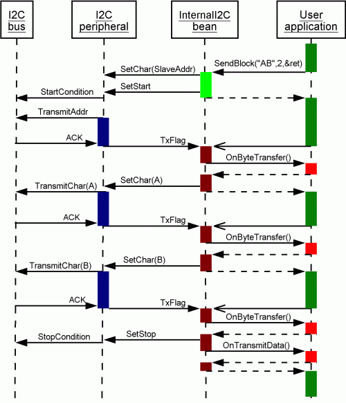
This chart shows sequence of data sending communication flow in the master mode when the address of the slave is sent as an ordinary data byte. In this case OnByteTransfer event is also called after address transmission. If the peripheral supports automatic slave address sending (special address register), OnByteTransfer event is not called after address transmission. See version specific info on General Info page.
 |
(2) Receiving data in the MASTER mode
Required component name is "I2C1"
and the following component settings: Mode selection - MASTER, Interrupt service - enabled.
Event OnReceiveData is called at the end of data reception. SelectSlave method is used for slave address selection and
RecvBlock method is used for data reception start.
The example demonstrates receiving of 2 bytes from the slave.
MAIN.C

byte flags;
byte err;
byte Data[2];
word ret;
#define SLAVE 0x08

void main(void)
{


  /* Set slave address */
  (void)I2C1_SelectSlave(SLAVE);

  /* Clear "Complete" flag */
  flags = 0;

  /* Receive bytes in master mode */
  err=I2C1_RecvBlock(&Data,2,&ret);
  if(err!=ERR_OK) {
    /* Handle an error */
  }

  /* Wait for communication complete */
  while(!flags) ;

  /* Now Data field contains received values */

}


EVENTS.C

extern byte flags;

void I2C1_OnReceiveData(void)
{
  flags = 1;		 /* Set "Complete" flag */
}
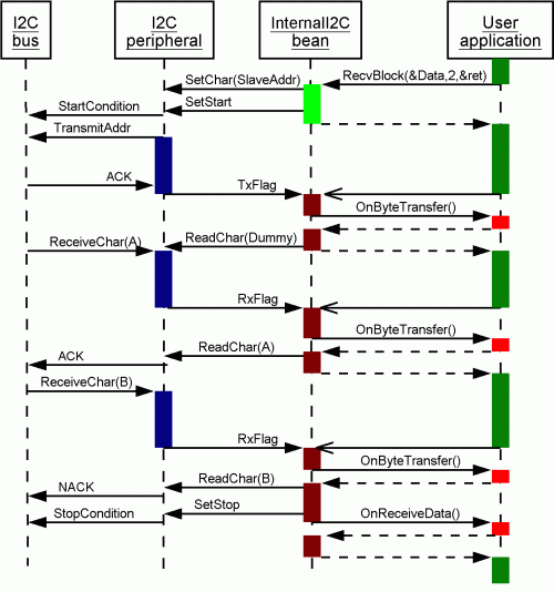
This chart shows a sequence of data receiving communication flow in the master mode if the address of the slave is sent as an ordinary data byte. In this case OnByteTransfer event is also called after address transmission. If the peripheral supports automatic slave address sending (special address register), OnByteTransfer event is not called after address transmission. See version specific info on General Info page.
 |
(3) Sending data in the SLAVE mode
Required component name is "I2C1"
and the ollowing component settings: Mode selection - SLAVE, Output buffer size - 3.
OnTxchar event is sent after each byte sending. OnFreeTxBuf event is called when last byte from the buffer was sent.
OnTxEmptyChar event is called when no data is available and Empty character must be sent.
SendBlock method is used to prepare data to the output buffer.
The example demonstrates how the slave prepares 2 bytes into the output buffer. Then the master requests 3 bytes to be sent by slave, i.e., the last sent character is the Empty character.
MAIN.C

byte flags;
byte err;
byte data[]="AB";
word ret;

#define TX_CHAR     1    /* Flag for OnTxChar event */
#define BUFFER_FREE 2    /* Flag for OnFreeTxBuf event */
#define TX_EMPTY    4    /* Flag for OnTxEmpty event */

void main(void)
{

  /* Clear "empty" flag */
  flags = 0;

  /* Send bytes in slave mode (prepare to the output buffer) */
  err=I2C1_SendBlock(&data,2,&ret);
  if(err!=ERR_OK) {
    /* Handle an error */
  }

  /* Scan the events */
  do {
    if(flags & TX_CHAR) {
      /* Now all bytes has been sent */
      flags &= ~TX_CHAR;
    }
    if(flags & BUFFER_FREE) {
      /* Now buffer is empty, last character has been sent */
      flags &= ~BUFFER_FREE;
    }
    if(flags & TX_EMPTY) {
      /* Buffer is empty, empty character has been sent */
      flags &= ~TX_EMPTY;
      break;
    }
  }while(1);

}


EVENTS.C

extern byte cntr;
extern byte flags;

void I2C1_OnTxChar(void)
{
  flags |= TX_CHAR;	 /* Set the "TX" flag */
}

void I2C1_OnFreeTxBuf(void)
{
  flags |= BUFFER_FREE;  /* Set the "Buffer Free" flag */
}

void I2C1_OnTxEmptychar(void)
{
  flags |= TX_EMPTY;	 /* Set the "empty" flag */
}
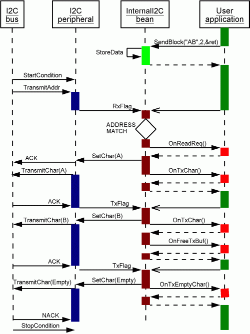
This chart shows sequence of data sending communication flow in the slave mode.
 |
(4) Receiving data in the SLAVE mode
Required component name is "I2C1"
and the following component settings: Mode selection - SLAVE, Input buffer size - 2.
OnRxchar event is sent after each byte reception. OnFullRxBuf event is called when input data buffer is full.
RecvBlock method is used for getting the received data from the input buffer.
The example demonstrates how the slave receives 3 bytes from the master. As the slave has only 2 bytes input buffer, OnError event is called and the last received character is lost.
MAIN.C

byte flags;
byte errFlags;
byte err;
byte data[2];
word ret;

void main(void)
{

  flags = 0;       /* Clear flags */
  errFlags = 0;

  while(!flags);   /* Wait for full buffer */

  /* Now the buffer is full. */
  /* If the input buffer was read now the error would not occur */

  /* For demo purpose, wait for error flag */
  /* One more byte has to be received */
  while(!errFlags);

  /* Receive bytes in slave mode (read the input buffer) */
  err=I2C1_RecvBlock(&data,2,&ret);
  if(err!=ERR_OK) {
    /* Handle an error */
  }


}


EVENTS.C

extern byte flags;

void I2C1_OnFullRxBuf(void)
{
  flags = 1;		 /* Set the "full" flag */
}

void I2C1_OnError(void)
{
  errFlags = 1;		 /* Set the "error" flag */
}
This chart shows sequence of data receiving communication flow in the slave mode.
 |
(5) Sending data in the MASTER mode without interrupts
Required component name is "I2C1"
and the following component settings: Mode selection - MASTER, Interrupt service - disabled.
SelectSlave method is used for slave address selection and
SendBlock method is used for data sending.
The example demonstrates sending of 2 bytes to the slave.
MAIN.C

byte err;
byte Data[]="AB";
word ret;
#define SLAVE 0x08

void main(void)
{


  /* Set slave address */
  (void)I2C1_SelectSlave(SLAVE);

  /* Send bytes in master mode */
  err=I2C1_SendBlock(&Data,2,&ret);
  if(err!=ERR_OK) {
    /* Handle an error */
  }


}
This chart shows a sequence of data sending communication flow in the master mode without interrupts if the address of the slave is sent as an ordinary data byte. In this case OnByteTransfer event is also called after address transmission. If the peripheral supports automatic slave address sending (special address register), OnByteTransfer event is not called after address transmission. See version specific info on General Info page.
 |
(6) Receiving data in the MASTER mode without interrupts
Required component name is "I2C1"
and the following component settings: Mode selection - MASTER and Interrupt service - disabled.
SelectSlave method is used for slave address selection and
RecvBlock is used for data reception.
The example demonstrates receiving of 2 bytes from the slave.
MAIN.C

byte err;
byte Data[2];
word ret;
#define SLAVE 0x08

void main(void)
{


  /* Set slave address */
  (void)I2C1_SelectSlave(SLAVE);

  /* Receive bytes in master mode */
  err=I2C1_RecvBlock(&Data,2,&ret);
  if(err!=ERR_OK) {
    /* Handle an error */
  }

  /* Now Data field contains received values */


}
This chart shows sequence of data receiving communication flow in the master mode without interrupts if the address of the slave is sent as an ordinary data byte. In this case OnByteTransfer event is also called after address transmission. If the peripheral supports automatic slave address sending (special address register), OnByteTransfer event is not called after address transmission. See version specific info on General Info page.
 |
(7) Slave Selection and general call in the MASTER mode.
Required component name is "I2C1"
and the following component settings: Mode selection - MASTER and Interrupt service - disabled.
SelectSlave method is used for slave address selection in 7-bit addressing mode,
SelectSlave10 method is used for slave address selection in 10-bit addressing mode (available if supported by HW),
SelectSpecialCommand method is used for special command (address) selection such as General call address (available if supported by HW),
SendBlock is used for data sending.
The example demonstrates selection of a slave address, general call address selection and sending of 2 bytes from the master.
MAIN.C

byte err;
byte Data[2] = {5,6};
word ret;
#define SLAVE_7 0x08   /* A slave address - 7-bit addressing mode */
#define SLAVE_10 0x97   /* A slave address - 10-bit addressing mode */

void main(void)
{


  /* Set slave address - 7-bit addressing mode */
  /* All subsequent calls of SendChar, SendBlock, RecvChar, RecvBlock */
  /* will use selected address and 7-bit addressing mode */
  (void)I2C1_SelectSlave(SLAVE_7);

  /* Send bytes in master mode to the selected slave - 7-bit address */
  err=I2C1_SendBlock(&Data,2,&ret);
  if(err!=ERR_OK) {
    /* Handle an error */
  }

  /* Set slave address - 10-bit addressing mode */
  /* All subsequent calls of SendChar, SendBlock, RecvChar, RecvBlock */
  /* will use selected address and 10-bit addressing mode */
  (void)I2C1_SelectSlave10(SLAVE_10);

  /* Send bytes in master mode to the selected slave - 10-bit address */
  err=I2C1_SendBlock(&Data,2,&ret);
  if(err!=ERR_OK) {
    /* Handle an error */
  }

  /* Set slave address - general call address */
  /* All subsequent calls of SendChar, SendBlock will use general call address */
  /* Calls of RecvChar, RecvBlock are not available, it will return ERR_NOTAVAIL  */
  (void)I2C1_SelectSpecialCommand(0);

  /* Send bytes in master mode to the selected slave - general call address */
  err=I2C1_SendBlock(&Data,2,&ret);
  if(err!=ERR_OK) {
    /* Handle an error */
  }


}
(8) Communication with external serial EEPROM memory.
Required component name is "I2C1"
and the following component settings: Mode selection - MASTER, Interrupt service - enabled,
Automatic Stop condition - no.
SelectSlave method is used for slave address selection in 7-bit addressing mode,
SendBlock method is used for data sending and RecvBlock used for data receiving.
Cpu_Delay100US - method of the CPU component used for time delay.
The example shows the communication with external serial EEPROM memory, specifically 24C128 device.
MAIN.C

byte buffer[3];
word sent;
byte data;
byte err;
extern volatile byte TransmitComplete;

void main(void)
{

  //WRITE DATA
  TransmitComplete = 0;
  err = I2C1_SelectSlave(0x50);           //Select address of the EEPROM device (not required if only one device on the bus)
  buffer[0] = 0;                          //most significant byte of storage address
  buffer[1] = 0x50;                       //least significant byte of storage address
  buffer[2] = 0x10;                       //data
  err = I2C1_SendBlock(buffer, 3, &sent); //send storage address and data to the EEPROM
  while(!TransmitComplete){}              //wait for communication completition
  err = I2C1_SendStop();                  //Send STOP condition

  Cpu_Delay100US(100); //10ms delay for EEPROM to complete write cycle - for more details see EEPROM datasheet

  //READ DATA
  TransmitComplete = 0;
  buffer[0] = 0;                          //most significant byte of storage address
  buffer[1] = 0x50;                       //least significant byte of storage address
  err = I2C1_SendBlock(buffer, 2, &sent); //send address to the EEPROM
  while(!TransmitComplete){}
  err = I2C1_RecvChar(&data);             //read data from EEPROM

}

EVENTS.C

volatile byte TransmitComplete;

void I2C1_OnTransmitData(void)
{
  TransmitComplete = 1;
}