|
User manual |
| |
Dialog Box for Timing Settings
The Timing dialog box provides a user-friendly interface for the settings of component timing features. When clicking on the  button of a timing item in the Component Inspector, the timing dialog box is displayed.
- Target CPU in the Project Panel
- Used peripherals in the component's properties
- Supported speed modes in the component's properties
The settings are instantly validated according to the Processor Expert timing model.
Timing Dialog Controls
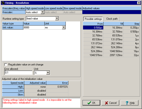 |
| Figure 1 - Timing Settings Dialog |
Prescalers table
Note: This table is visible only in Advanced or Expert view mode and if it is possible to select a prescaler for the selected peripheral.
This table occupies the topmost part of the window. It shows a clock source and prescaler(s) values related to the currently edited timing value (see the section Timing values table for details). A presence and number of rows in the table are optional and depend on the hardware structure and a type of the configured value.
The table allows the user to configure his/her requirements on the prescalers. Autoselect means that the value is configured automatically by Processor Expert to achieve the requested timing. Otherwise, if there are some values set manually, only these values will be used and possible timing values are limited to the values that can be achieved with the manually set clock source and/or prescaler values.
The table contains a row for each prescaler which is used by the device selected for the component. Each column contains a value corresponding to one speed mode except the last column which shows values of the prescalers that are really set. It's possible to adjust the values only in the columns of the speed modes that are enabled.
The table can contain the following rows:
- Clock source - the clock source is fixed for each speed mode. Even if the runtime setting is used, this value has to be the same for all values from the list (in case of "from a list of values") or for the whole interval range (in case of "from interval"). See below for details on Runtime setting.
- Prescaler, Pre-prescaler - the prescaler influencing the clock of the peripheral selected for the component. If the runtime setting "from a list of values" is used, this value can be different for every item of the list. Otherwise it has to be fixed. In some cases it's necessary to select the clock source before adjusting this value.
Runtime setting configuration
Note: Runtime setting cannot be selected in the BASIC view mode.
Runtime setting type selection determines how the timing setting can be modified at runtime. The following options are available:
- fixed value: the timing cannot be changed at runtime.
- from a list of values: allows to change the timing by selecting one of predefined values (from the list) using component method "SetXXXMode". This method sets the values(s) corresponding to the selected timing into appropriate prescaler and other peripheral register(s). The values (modes) in the list can be added/removed by editing the timing values table.
- from interval: allows to change a timing freely within a selected interval, while all values of the interval are selected with specified precision. Prescaler value is fixed in this mode, timing is set only using compare/reload registers value. It means that there must be possible to set all values within the interval by using the same prescaler.
Please note that this kind of runtime setting requires runtime computations that can be time and space consuming and may not be supported on all microcontrollers.
Note: Some of the methods used for runtime setting of timing will be enabled only if the appropriate runtime setting type is selected.
Timing values table
This table allows to set or modify a requested value(s) for the configured timing. Each row represents one time value and the number of rows depends on the selected type of runtime setting.
- For the option "fixed value" there is only one row (Init.Value) containing the fixed initialization value.
- For the option "from a list of values" there is one row for each of the possible timing modes. Please see the section There is possible to enter 16 possible values (modes). The empty fields are ignored. The user can drag and drop rows within the table to change their order. Runtime setting configuration within this chapter for more information.
- For the option "from interval" the table has three rows that contain the Initial value, low limit and high limit of the interval. Please see the section Runtime setting configuration within this chapter for details on this type of runtime setting.
- Value - Fill in a requested time value (without units). The drop-down arrow button allows to display a list of neighboring values and the user can select one of them. There is also possible to set the value by double-clicking on a value from the possible settings table (see below).
- Units - units for the value. When the Recalculate on unit change check-box below the table is checked, the value (in the previous column) is automatically re-calculated to be the same in the newly selected units.
Timing precision configuration
It is possible to specify desired precision of the timer settings by using one of the following settings (which one is used depends on the type of the timing) :
- The field Error allowed allows to specify a tolerated difference between the real timing and the requested value. The Unit field allows to specify the units for the error allowed field (time units or a percentage of the requested value).
- The Min. resolution field is used for setting interval or capture component timing. Allows the user to specify maximal acceptable length of one tick of the timer.
In the case of interval settings type, the % of low limit (percentage of the low limit value) can be used as the unit for this value.
Minimal timer ticks
Note: This item is available only for setting of period in components where it's meaningful (e.g. PWM, PPG).
This item allows to set a minimal number of timer-ticks in period. It means that it will be possible to set a duty of the output signal to at least the specified number of distinct values for any period of the output signal at runtime. Value 0 means no requirements for the timer settings.
Adjusted values
This table displays a real values for each speed mode the currently selected row in the Timing values table. These values are computed from the chosen on-chip peripheral settings, selected prescaler(s) value and the difference between a value selected by the user and the real value.
Status box
The status box displays a status of the timing setting(s). If the timing requirements are impossible to meet, a red error message is displayed, otherwise it's blank and gray.
Possible settings table
This table is displayed on the right part of the timing dialog if the the button Possible settings on the top is pressed. The table shows values supported by the target CPU for the selected peripheral.
If there are only individual values available to set, the table contains a list of values - each row represents one value. If there are intervals with a constant step available, each row contains one of the intervals with three values: From, Till - minimum and maximum value, Step - a step between values within the interval.
The way the values are displayed may be dependent on
- Runtime setting type - if it's "fixed value" or "from list of values" - the values present in more rows (overlapping intervals) are shown only once. If the "from time interval" runtime setting type is used, all intervals possible to set by various prescalers combinations are shown, even if they overlap. It's because intervals can differ in resolution (i.e. number of individual timing steps that can be achieved within them).
- Timing unit - if a frequency unit is used (e.g. Hz, kHz), the step column is not visible
By clicking on the table header, there is possible to order the rows by the selected column. By clicking the same column again, the user can switch between ascending or descending order.
Double clicking on a value will place the value into the currently edited row within the Timing values table.
The values listed in the possible settings table depend on the following timing settings:
- prescalers
- minimal timer ticks
- selected CPU
- selected peripheral
- speed-modes enabled for the component
The table contains a speed mode tabs (speed modes and related settings are supported only in EXPERT view mode) that allow to filter the displayed intervals for a specific speed mode or show intersection of all. Please note that the intersection contains only a values that can be set in all speed modes with absolute precision (without any error), so some values that are still valid due to non-zero Error allowed value are not shown.
Clock path
Note: This table is available in Advanced or Expert view modes only.
This table is displayed on the right part of the timing dialog if the the button Clock path on the top is pressed. Each row of the table represents a device influencing a clock on the path from the clock source on the first row (e.g. the crystal, internal oscillator or PLL) to the peripheral or a part of it. The last row contains total divider (a total ratio between the source clock and the resulting peripheral clock) in the form of *{mult}/{div} where {mult} is multiplier and {div} is divider or /{div} if no multiplier is present.
When multiple speed modes are used, it's possible to see the clock path in the individual speed modes by switching the tabs at the bottom.
Please note that the clock path may not be displayed correctly in case that there is not possible to set the required timing (i.e. when error message is displayed).
The table contains the following columns:
- Clock device icon - a symbol representing a type of the clock device.
- Name - name of the clock source, prescaler or other timing device
- Presc.value - If the row represents division or multiplication, this field contains a value of of divisor/multiplier for the clock signal. Divisor and multiplier are distinguished by icon and hint text.
- Frequency - a clock frequency on the output from the clock device
Note: Some devices shown in the clock path are not physically present on the CPU but are only a necessary part of a virtual model that allows to represent a real timing behavior. The prescaler values in rows may not match the values exactly written into the control registers (e.g. compare/reload) but they are clock divisor values used by the timing model. Also if the component uses virtual clock device as a clock source (RTIShared), there is a device named SW extension that represent a divisor provided by software counter.
PROCESSOR EXPERT is trademark of Freescale Semiconductor, Inc.