| MeasurementEngine | |
|
|

Mandatory peripherals:
ADC (Analog-to-Digital Converter),
PDB (Programmable Delay Block),
Optional peripherals:
GPIO (General purpose Input/Output),
DAC (Digital-to-Analog Converter),
VREF (Voltage Reference Output),
TOD (Time of day),
OPAMP (Operational Amplifier),
TRIAMP (Trans-Impedance Amplifier).
One of the advantages of the ME component is to highlight how listed devices upon can facilitate all stages of the measurement, including
checking of setting all cooperatives modules. The goal of the ME component is to centralize and consolidate all the functions needed to
create an 'Analog Front End'.
Note:
This component does not support CPU speed modes. The timing setting needn´t be preserved after switching into a speed mode - in this
case the user has to ensure properly switching by his/her own code.
ME component consists of 4 parts
Trigger configurationThis part controls the ADC triggering according the user configuration. More detailed information about provided triggers are in ADC triggers description chapter.
Signal Biasing
This part controls output peripherals like DAC module, VREF module, and GPIO module.
Signal Conditioning
For conditioning purposes ME component provides TRIAMP module to convert input currents into voltages that can be measured with the ADC module and OPAMP module to perform many different OPAMP configurations (Inverting amplifier, Non-inverting amplifier, Buffer, etc.).
Signal Measurement
The user can configure ADC to measure pin, internal signal, set of pins, internal signals, or combination of of these sources. In case that a internal signal is selected and a appropriate module is not currently (in design time) properly configured (enabled) to providing this signal, the warning will be reported by appropriate module.
After the proper configuration in this section the user should decide which module (PDB, TOD, etc) to use for triggering of ADC module.
Trigger configuration overview
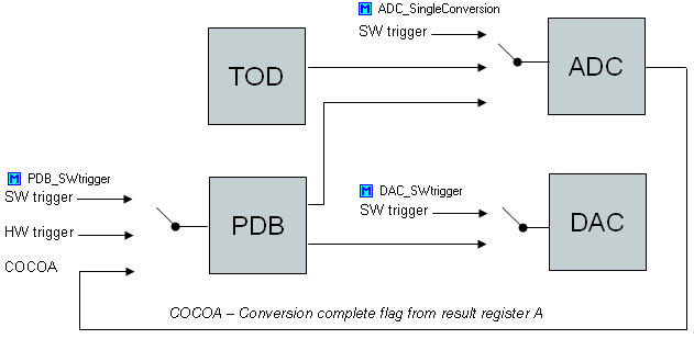
Figure: Trigger configuration overview on MCF51MM/JE and HCS08MM/JE families
ADC triggers description
PDB (Programmable Delay Block)
PDB module is a key module in the Measurement engine component. This simple timer is used to control the hardware triggering of the
ADC module and optionaly of the DAC module.
In case that PDB module supports DAC triggering - precise timing between DAC updates and ADC conversions
can be achieved.
Main function of the PDB module is providing triggers to ADC module
according to selected configuration (by comparasion with modules that can be used to ADC triggering - PDB module supports handling of all ADC result registers).
Provided set of properties depends on selected derivative.
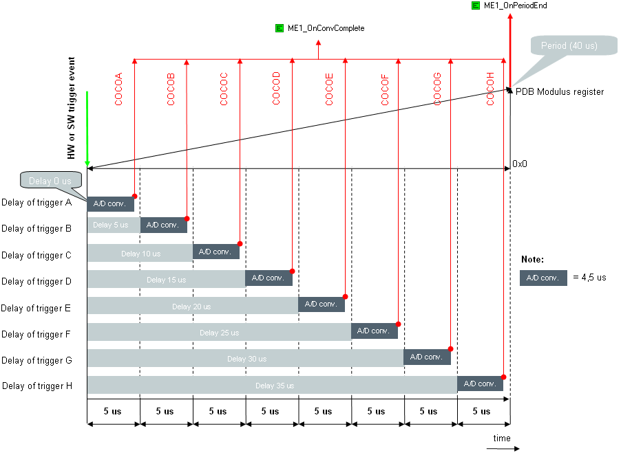
Figure: Use case of PDB module used for triggering of ADC module
TOD (Time of day)
TOD module is an optional trigger of ADC module in Measurement engine component. This simple timer is used to control the hardware triggering of the ADC module. The typical application with TOD module is to use the ADC module for the VDD measurements. TOD module provides triggers to ADC module according to selected value in Period property.
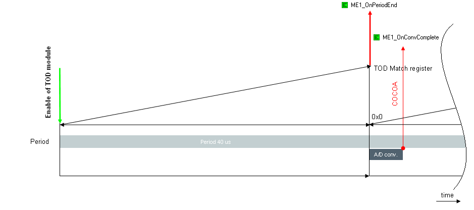
Figure: Use case of TOD module used for triggering of ADC module