# ESP32-S USB Dongle Solution
## 1.Overview
This example shows how to set up ESP32-S chip to work as a USB Dongle Device.
Supports the following functions:
* Support Host to surf the Internet wirelessly via USB-ECM/RNDIS.
* Add BLE devices via USB-BTH, support scan, broadcast, connect and other functions.
* Support Host to communicate and control ESP32-S series devices via USB-CDC or UART.
* Support Host to upgrade device using USB-DFU.
* Support system commands and Wi-Fi control commands. It uses FreeRTOS-Plus-CLI interfaces, so it is easy to add more commands.
* Support hot swap.
## 2.How to use example
### 2.1 Hardware Preparation
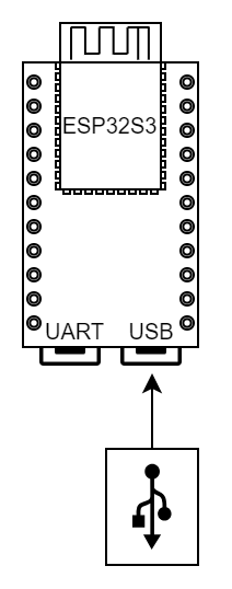
Any ESP boards that have USB-OTG supported.
* ESP32-S2
* ESP32-S3
### 2.2 Hardware Connection
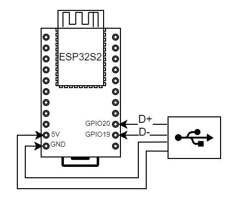
Pin assignment is only needed for ESP chips that have an USB-OTG peripheral. If your board doesn't have a USB connector connected to the USB-OTG dedicated GPIOs, you may have to DIY a cable and connect **D+** and **D-** to the pins listed below.
```
ESP BOARD USB CONNECTOR (type A)
--
| || VCC
[USBPHY_DM_NUM] ------> | || D-
[USBPHY_DP_NUM] ------> | || D+
| || GND
--
```
Refer to `soc/usb_pins.h` to find the real GPIO number of **USBPHY_DP_NUM** and **USBPHY_DM_NUM**.
| | USB_DP | USB_DM |
| ----------- | ------ | ------ |
| ESP32-S2/S3 | GPIO20 | GPIO19 |
* ESP32-S2-Saola
 * ESP32-S3 DevKitC
 ### 2.3 Software Preparation
* Confirm that the ESP-IDF environment is successfully set up.
```
>git checkout release/v4.4
>git pull origin release/v4.4
>git submodule update --init --recursive
>
```
* To add ESP-IDF environment variables. If you are using Linux OS, you can follow below steps. If you are using other OS, please refer to [Set up the environment variables](https://docs.espressif.com/projects/esp-idf/en/latest/esp32/get-started/index.html#step-4-set-up-the-environment-variables).
```
>cd esp-idf
>./install.sh
>. ./export.sh
>
```
* Set the compilation target to `esp32s2` or `esp32s3`
```
>idf.py set-target esp32s2
>
```
### 2.4 Project Configuration


Currently USB-Dongle supports the following four combination options.
| ECM/RNDIS | BTH | CDC | UART | DFU |
| :-------: | :--: | :--: | :--: | :--: |
| √ | | | √ | √ |
| √ | | √ | | √ |
| √ | √ | | √ | √ |
| | √ | | √ | √ |
* UART is disabled by default when CDC is enabled.
* UART can be used for command communication, and you can also use Bluetooth for communication.
* The project enables ECM and CDC by default.
* You can select USB Device through `component config -> TinyUSB Stack`.
* When ECM/RNDIS and BTH are enabled at the same time, it is recommended to disable CDC, use UART to send commands, and configure the serial port through `Example Configuration`.
>Due to current hardware limitations, the number of EndPoints cannot exceed a certain number, so ECM/RNDIS, BTH, and CDC should not be all enabled at the same time.
### 2.5 build & flash & monitor
You can use the following command to build and flash the firmware.
```
>idf.py -p (PORT) build flash monitor
>
```
* Replace ``(PORT)`` with the actual name of your serial port.
* To exit the serial monitor, type `Ctrl-]`.
### 2.6 User Guide
1. After completing above preparation, you can connect PC and your ESP device with USB cable.
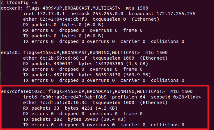
2. You can see a USB network card and a bluetooth device on your PC.
* Show network devices
```
>ifconfig -a
>
```
### 2.3 Software Preparation
* Confirm that the ESP-IDF environment is successfully set up.
```
>git checkout release/v4.4
>git pull origin release/v4.4
>git submodule update --init --recursive
>
```
* To add ESP-IDF environment variables. If you are using Linux OS, you can follow below steps. If you are using other OS, please refer to [Set up the environment variables](https://docs.espressif.com/projects/esp-idf/en/latest/esp32/get-started/index.html#step-4-set-up-the-environment-variables).
```
>cd esp-idf
>./install.sh
>. ./export.sh
>
```
* Set the compilation target to `esp32s2` or `esp32s3`
```
>idf.py set-target esp32s2
>
```
### 2.4 Project Configuration


Currently USB-Dongle supports the following four combination options.
| ECM/RNDIS | BTH | CDC | UART | DFU |
| :-------: | :--: | :--: | :--: | :--: |
| √ | | | √ | √ |
| √ | | √ | | √ |
| √ | √ | | √ | √ |
| | √ | | √ | √ |
* UART is disabled by default when CDC is enabled.
* UART can be used for command communication, and you can also use Bluetooth for communication.
* The project enables ECM and CDC by default.
* You can select USB Device through `component config -> TinyUSB Stack`.
* When ECM/RNDIS and BTH are enabled at the same time, it is recommended to disable CDC, use UART to send commands, and configure the serial port through `Example Configuration`.
>Due to current hardware limitations, the number of EndPoints cannot exceed a certain number, so ECM/RNDIS, BTH, and CDC should not be all enabled at the same time.
### 2.5 build & flash & monitor
You can use the following command to build and flash the firmware.
```
>idf.py -p (PORT) build flash monitor
>
```
* Replace ``(PORT)`` with the actual name of your serial port.
* To exit the serial monitor, type `Ctrl-]`.
### 2.6 User Guide
1. After completing above preparation, you can connect PC and your ESP device with USB cable.
2. You can see a USB network card and a bluetooth device on your PC.
* Show network devices
```
>ifconfig -a
>
```
 * Show bluetooth device
```
>hciconfig
>
```

Show USB-CDC device
```
>ls /dev/ttyACM*
>
```

3. The PC can communicate with the ESP board through the USB ACM port or UART. And you can use ``help`` command to view all commands supported.
> When communicating with ESP device, add **LF(\n)** at the end of the command
4. If USB-RNDIS is enabled, you can connect ESP device to AP by commands.
* [Connect to target AP by sta command](./Commands_EN.md#3sta)
* [Connect to target AP by startsmart command (SmartConfig)](./Commands_EN.md#5smartconfig)
### 2.7 Common network device Problems
#### Windows
Windows platform only supports RNDIS, USB ECM is not recognized.
#### MAC
MAC platform only supports ECM, USB RNDIS is not recognized.
#### Linux
Linux platform support both ECM and RNDIS. However, if RNDIS is used, network devices in Linux do not proactively obtain IP addresses when switching between different routers.
If embedded Linux is used and network devices are not displayed, the preceding two modules may not be enabled in the kernel. The following two configuration items are enabled in the Linux kernel to support CDC-ECM and RNDIS respectively.
```
Device Drivers --->
Network Device Support --->
Usb Network Adapters --->
Multi-purpose USB Networking Framework --->
CDC Ethernet Support
Host For RDNIS and ActiveSync Devices
```
If you are sure that the network device cannot be seen after the preceding modules are enabled, run the `dmesg` command to view the kernel information to check whether ESP32-S USB network devices are detected in the Linux kernel and whether error messages are displayed.
## 3. Connect to a Wi-Fi AP
The example provides two methods to connect ESP device to a Wi-Fi AP.
### [Method 1. Connect to target AP by `sta` command](./Commands_EN.md#3sta)
**Command Example**
```
sta -s -p []
```
**Notes**
* `password` is optional
### [Method 2. Connect to target AP by startsmart command (SmartConfig)](./Commands_EN.md#5smartconfig)
(1) Hardware Required
Download ESPTOUCH APP from app store: [Android source code](https://github.com/EspressifApp/EsptouchForAndroid) [iOS source code](https://github.com/EspressifApp/EsptouchForIOS) is available.
(2) Make sure your phone connect to the target AP (2.4GHz).
(3) Open ESPTOUCH app and input password.
(4) Send commands via USB ACM port
**Example**
```
smartconfig 1
```
## 4.Command introduction
[Commands](./Commands_EN.md)
Note: Wi-Fi commands can only be used when USB Network Class is enabled
## 5. How to use USB-DFU to upgrade device
Before using DFU to upgrade ES[32-S device, ensure that the DFU feature has been enabled in the configuration item.
```
component config -> TinyUSB Stack -> Use TinyUSB Stack -> Firmware Upgrade Class (DFU) -> Enable TinyUSB DFU feature
```
#### Ubuntu
You need to install the DFU tool first in Ubuntu.
```
sudo apt install dfu-util
```
Run the following command to upgrade.
```
sudo dfu-util -d -a 0 -D
```
**Notes**
- VendorID is USB vendor ID, the default value 0x303A
- OTA_BIN_PATH is the upgrade firmware
Run the following command to upload.
```
sudo dfu-util -d -a 0 -U
```
**Notes**
- VendorID is USB vendor ID, the default value 0x303A
- Read firmware from device into OTA_BIN_PATH
#### Windows
1. On Windows you need to download [dfu-util](http://dfu-util.sourceforge.net/releases/dfu-util-0.9-win64.zip) first.
2. `dfu-util` uses libusb to access the device. You have to register on Windows the device with the WinUSB driver. Installation using [Zadig](http://zadig.akeo.ie/) tool is recommended.
3. Open the command window, run the following commands using `dfu-util.exe`.
```
dfu-util.exe -d -a 0 -D
```
**Notes**
- VendorID is USB vendor ID, the default value 0x303A
- OTA_BIN_PATH is the upgrade firmware
#### Common problems
1. Please refer to [this link](https://support.particle.io/hc/en-us/articles/360039251394-Installing-DFU-util) for the installation error of `dfu-util` tool on each platform.
2. "No DFU capable USB device available" means `dfu-util` does not detect the DFU device of the ESP32-S chip. Ensure that the DFU feature is enabled in the configuration item.
In Linux platform, make sure you are using administrator rights.
* Show bluetooth device
```
>hciconfig
>
```

Show USB-CDC device
```
>ls /dev/ttyACM*
>
```

3. The PC can communicate with the ESP board through the USB ACM port or UART. And you can use ``help`` command to view all commands supported.
> When communicating with ESP device, add **LF(\n)** at the end of the command
4. If USB-RNDIS is enabled, you can connect ESP device to AP by commands.
* [Connect to target AP by sta command](./Commands_EN.md#3sta)
* [Connect to target AP by startsmart command (SmartConfig)](./Commands_EN.md#5smartconfig)
### 2.7 Common network device Problems
#### Windows
Windows platform only supports RNDIS, USB ECM is not recognized.
#### MAC
MAC platform only supports ECM, USB RNDIS is not recognized.
#### Linux
Linux platform support both ECM and RNDIS. However, if RNDIS is used, network devices in Linux do not proactively obtain IP addresses when switching between different routers.
If embedded Linux is used and network devices are not displayed, the preceding two modules may not be enabled in the kernel. The following two configuration items are enabled in the Linux kernel to support CDC-ECM and RNDIS respectively.
```
Device Drivers --->
Network Device Support --->
Usb Network Adapters --->
Multi-purpose USB Networking Framework --->
CDC Ethernet Support
Host For RDNIS and ActiveSync Devices
```
If you are sure that the network device cannot be seen after the preceding modules are enabled, run the `dmesg` command to view the kernel information to check whether ESP32-S USB network devices are detected in the Linux kernel and whether error messages are displayed.
## 3. Connect to a Wi-Fi AP
The example provides two methods to connect ESP device to a Wi-Fi AP.
### [Method 1. Connect to target AP by `sta` command](./Commands_EN.md#3sta)
**Command Example**
```
sta -s -p []
```
**Notes**
* `password` is optional
### [Method 2. Connect to target AP by startsmart command (SmartConfig)](./Commands_EN.md#5smartconfig)
(1) Hardware Required
Download ESPTOUCH APP from app store: [Android source code](https://github.com/EspressifApp/EsptouchForAndroid) [iOS source code](https://github.com/EspressifApp/EsptouchForIOS) is available.
(2) Make sure your phone connect to the target AP (2.4GHz).
(3) Open ESPTOUCH app and input password.
(4) Send commands via USB ACM port
**Example**
```
smartconfig 1
```
## 4.Command introduction
[Commands](./Commands_EN.md)
Note: Wi-Fi commands can only be used when USB Network Class is enabled
## 5. How to use USB-DFU to upgrade device
Before using DFU to upgrade ES[32-S device, ensure that the DFU feature has been enabled in the configuration item.
```
component config -> TinyUSB Stack -> Use TinyUSB Stack -> Firmware Upgrade Class (DFU) -> Enable TinyUSB DFU feature
```
#### Ubuntu
You need to install the DFU tool first in Ubuntu.
```
sudo apt install dfu-util
```
Run the following command to upgrade.
```
sudo dfu-util -d -a 0 -D
```
**Notes**
- VendorID is USB vendor ID, the default value 0x303A
- OTA_BIN_PATH is the upgrade firmware
Run the following command to upload.
```
sudo dfu-util -d -a 0 -U
```
**Notes**
- VendorID is USB vendor ID, the default value 0x303A
- Read firmware from device into OTA_BIN_PATH
#### Windows
1. On Windows you need to download [dfu-util](http://dfu-util.sourceforge.net/releases/dfu-util-0.9-win64.zip) first.
2. `dfu-util` uses libusb to access the device. You have to register on Windows the device with the WinUSB driver. Installation using [Zadig](http://zadig.akeo.ie/) tool is recommended.
3. Open the command window, run the following commands using `dfu-util.exe`.
```
dfu-util.exe -d -a 0 -D
```
**Notes**
- VendorID is USB vendor ID, the default value 0x303A
- OTA_BIN_PATH is the upgrade firmware
#### Common problems
1. Please refer to [this link](https://support.particle.io/hc/en-us/articles/360039251394-Installing-DFU-util) for the installation error of `dfu-util` tool on each platform.
2. "No DFU capable USB device available" means `dfu-util` does not detect the DFU device of the ESP32-S chip. Ensure that the DFU feature is enabled in the configuration item.
In Linux platform, make sure you are using administrator rights.