
Copyright 2017 STMicroelectronics
The STM32CubeH7 Firmware package comes with a rich set of examples running on STMicroelectronics boards, organized by board and provided with preconfigured projects for the main supported toolchains.
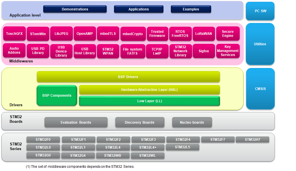


1. Case of a single core project, STM32H743I-EVAL board:
a. Browse to \\Projects\\STM32H743I-EVAL\\Examples.
b. Open \\GPIO, then the \\GPIO_EXTI folder.
c. Open the project with your preferred toolchain.
d. Rebuild all files and load your image into target memory.
e. Run the example: each time you press the Tamper push-button, the LED1 will toggle (for more details, refer to the example readme file).
2. Case of a dual core project, example STM32H747I-EVAL board:
a. Browse to \\Projects\\STM32H747I-EVAL\\Examples.
b. Open \\GPIO, then the \\GPIO_EXTI folder.
c. Open the project with your preferred toolchain
d. For each target STM32H747I_EVAL_CM4 and STM32H747I_EVAL_CM7 (respectively for Cortex-M7 and Cortex-M4):
i. Rebuild all files and load your image into target memory
ii. After loading the two images, reset the board in order to boot (Cortex-M7) and CPU2 (Cortex-M4) at once
i. each time you press the Tamper push-button, :
a. LED1 toggles once (To indicated an EXTI interrupt for Cortex-M7)
b. LED3 toggles once (To indicated an EXTI interrupt for Cortex-M4)
ii. (for more details, refer to the example readme file).
3. Case of a value line project, STM32H750B-DK board:
a. Browse to Projects\\STM32H750B-DK\\Templates\ExtMem_Boot.
b. Open the ExtMem_Boot project with your preferred toolchain
c. Rebuild all files and load your image into target internal flash memory
d. Browse to \\Projects\\STM32H750B-DK\\Examples.
e. Open \\GPIO, then the \\GPIO_IOToggle folder.
f. Open the project with your preferred toolchain (keep the default configuration XIP_QSPI_InternalSRAM)
g. Rebuild all files and load your image into the external QSPI flash memory.
h. Run the example: LED1 will toggle infinitely each (for more details, refer to the example readme file).
Note : The principle of the STM32H750xx value line
applications is to execute user application from an external memory
(QSPI flash ore SDRAM, default is QSPI flash).
The Templates\ExtMem_Boot projects allows to boot from the STM32H750xx internal flash,
configure external memories then jump to user application located on
an external memory of the STM32H750B-DK board.
The provided examples can be tailored to run on any compatible hardware; user simply need to update the BSP drivers for his board, if it has the same hardware functions (LED, LCD display, pushbuttons...etc.). The BSP is based on a modular architecture that allows it to be ported easily to any hardware by just implementing the low level routines.
| Level | Module Name | Project Name | Description | STM32H7B3I-EVAL | STM32H7B3I-DK | STM32H750B-DK | STM32H747I-EVAL | STM32H747I-DISCO | STM32H745I-DISCO | STM32H743I-EVAL | STM32H735G-DK | NUCLEO-H7A3ZI-Q | NUCLEO-H745ZI-Q | NUCLEO-H743ZI | NUCLEO-H723ZG |
Templates |
- |
BootCM4_CM7 |
This project provides a reference template that can be used to build any firmware application where both cores are used. It is mainly dedicated for devices where CPU1 (Cortex-M7) and CPU2 (Cortex-M4) are booting at once (with respect to configured boot Flash options) System Init, System clock, voltage scaling and L1-Cache configuration are done by CPU1 (Cortex-M7). | - | - | - | X | X | X | - | - | - | X | - | - |
BootCM4_CM7Gated |
This project provides a reference template that can be used to build any firmware application where both cores are used. It is mainly dedicated for parts where CPU2 (Cortex-M4) is booting and CPU1(Cortex-M7)clock is gated. | - | - | - | X | X | X | - | - | - | X | - | - | ||
BootCM7_CM4Gated |
This project provides a reference template that can be used to build any firmware application where both cores are used. It is mainly dedicated for parts where CPU1 (Cortex-M7) is booting and CPU2(Cortex-M4)clock is gated. | - | - | - | X | X | X | - | - | - | X | - | - | ||
BootCM7_CM4Gated_RAM |
This project provides a reference template that can be used to build any firmware application where both cores are used. It is mainly dedicated for parts where CPU1 (Cortex-M7 in D1 Domain) is booting and CPU2(Cortex-M4 in D2 Domain) is gated (with respect to configured boot Flash options). | - | - | - | X | X | X | - | - | - | X | - | - | ||
ExtMem_Boot |
This directory contains a set of sources files and pre-configured projects that describes how to build an application for execution from external memory using the ExtMem_Boot firmware. | - | - | X | - | - | - | - | - | - | - | - | - | ||
Starter project |
This projects provides a reference template that can be used to build any firmware application. | X | X | - | - | - | - | X | X | X | - | X | X | ||
Template_Project |
This projects provides a reference template that can be used to build any firmware application with execution from external memory This projects is configured for STM32H750xx devices using STM32CubeH7 HAL and running on STM32H750B-DISCO board from STMicroelectronics. | - | - | X | - | - | - | - | - | - | - | - | - | ||
| Total number of templates: 25 | 1 | 1 | 2 | 4 | 4 | 4 | 1 | 1 | 1 | 4 | 1 | 1 | |||
Templates_LL |
- |
Starter project |
This projects provides a reference template through the LL API that can be used to build any firmware application. | X | X | - | X | X | X | X | X | X | X | X | X |
| Total number of templates_ll: 11 | 1 | 1 | 0 | 1 | 1 | 1 | 1 | 1 | 1 | 1 | 1 | 1 | |||
Examples |
- |
BSP |
This projects uses STM32CubeH7 HAL and BSP. It provides a description of how to use the different BSP drivers for each STM32H7 board. | X | X | X | X | X | X | X | X | X | X | X | X |
ADC |
ADC_AnalogWatchdog |
This example provides a short description of how to use the ADC peripheral to perform conversions with analog watchdog and out-of-window interruptions enabled. | - | - | - | - | - | - | X | X | X | - | X | - | |
ADC_DAC_Interconnect |
This example describes how to configure and connect DAC output to ADC input and use the analog watchdog to monitor signal behavior. | X | - | - | - | - | - | X | - | - | - | X | - | ||
ADC_DMA_Transfer |
How to configure and use the ADC to convert an external analog input and get the result using a DMA transfer through the HAL API. | X | - | - | - | - | - | X | X | X | - | X | - | ||
ADC_DifferentialMode |
This example describes how to configure and use the ADC2 to convert an external analog input in Differential Mode, difference between external voltage on VinN and VinP. | - | - | - | - | - | - | X | - | X | - | X | - | ||
ADC_DualModeInterleaved |
How to use two ADC peripherals to perform conversions in dual interleaved mode. | - | X | - | X | X | X | X | - | X | X | X | - | ||
ADC_InternalChannelConversion |
This example describes how to configure and use the ADC to retrieve an internal ADC channel. | - | - | - | - | - | - | X | - | - | - | X | - | ||
ADC_OverSampler |
This example describes how to configure and use the ADC to convert an external analog input combined with oversampling feature to increase resolution through the HAL API. | - | - | - | - | - | - | X | - | - | - | X | - | ||
ADC_Oversampling |
This example describes how to use a ADC peripheral with ADC oversampling. | - | - | - | - | - | - | - | - | X | - | - | - | ||
ADC_RegularConversion_Polling |
This example describes how to use the ADC in Polling mode to convert data through the HAL API. | - | - | - | - | - | - | X | - | - | - | X | - | ||
ADC_Regular_injected_groups |
This example provides a short description of how to use the ADC peripheral to perform conversions using the two ADC groups: regular group for ADC conversions on main stream and injected group for ADC conversions limited on specific events (conversions injected within main conversions stream). | - | - | - | - | - | X | X | - | - | - | X | - | ||
CEC |
CEC_DataExchange |
This example shows how to configure and use the CEC peripheral to receive and transmit messages. | - | - | - | - | - | - | X | - | - | - | - | - | |
COMP |
COMP_AnalogWatchdog |
How to use a pair of comparator peripherals to compare a voltage level applied on a GPIO pin to two thresholds: the internal voltage reference (VREFINT) and a fraction of the internal voltage reference (VREFINT/4), in interrupt mode. | X | - | - | - | - | - | X | - | - | - | X | X | |
COMP_Interrupt |
This example shows how to configure the COMP peripheral to compare the external voltage applied on a specific pin with the Internal Voltage Reference. | X | - | - | X | - | - | X | X | X | - | X | X | ||
COMP_OutputBlanking |
This example shows how to use the output blanking feature of COMP peripheral. | - | - | - | - | - | - | X | - | X | - | X | - | ||
CORDIC |
CORDIC_Sin_DMA |
How to use the CORDIC peripheral to calculate array of sines in DMA mode. | - | - | - | - | - | - | - | X | - | - | - | X | |
CRC |
CRC_Bytes_Stream_7bit_CRC |
How to configure the CRC using the HAL API. The CRC (cyclic redundancy check) calculation unit computes 7-bit CRC codes derived from buffers of 8-bit data (bytes). The user-defined generating polynomial is manually set to 0x65, that is, X^7 + X^6 + X^5 + X^2 + 1, as used in the Train Communication Network, IEC 60870-5[17]. | X | - | - | - | - | - | X | - | X | - | X | - | |
CRC_Data_Reversing_16bit_CRC |
How to configure the CRC using the HAL API. The CRC (cyclic redundancy check) calculation unit computes a 16-bit CRC code derived from a buffer of 32-bit data (words). Input and output data reversal features are enabled. The user-defined generating polynomial is manually set to 0x1021, that is, X^16 + X^12 + X^5 + 1 which is the CRC-CCITT generating polynomial. | - | - | - | - | - | - | - | X | - | - | - | - | ||
CRC_Example |
How to configure the CRC using the HAL API. The CRC (cyclic redundancy check) calculation unit computes the CRC code of a given buffer of 32-bit data words, using a fixed generator polynomial (0x4C11DB7). | X | - | - | - | - | - | X | X | X | - | X | X | ||
CRC_UserDefinedPolynomial |
How to configure and use the CRC calculation unit to compute an 8-bit CRC code for a given data buffer, based on a user-defined generating polynomial. The peripheral initialization is done using LL unitary service functions for optimization purposes (performance and size). | - | - | - | X | - | X | X | X | X | - | X | X | ||
CRYP |
CRYP_AESCCM_IT |
250 How to use the CRYPTO peripheral to encrypt/decrypt data(Plaintext/Ciphertext) in interrupt mode using AES with Combined Cipher Machine (CCM) then generate the authentication TAG . | X | - | - | - | - | - | X | - | - | - | - | - | |
CRYP_AESGCM |
How to use the CRYPTO peripheral to encrypt/decrypt data(Plaintext/Ciphertext) using AES Galois/counter mode (GCM)and generate the authentication TAG . | - | - | - | X | - | - | X | - | - | - | - | - | ||
CRYP_AESModes |
How to use the CRYP peripheral to encrypt/decrypt data(Plaintext/Ciphertext) using AES ECB, CBC and CTR algorithm. | - | - | - | - | - | - | X | - | - | - | - | - | ||
CRYP_AESModes_DMA |
How to use the CRYPTO peripheral to encrypt/decrypt data(Plaintext/Ciphertext) using AES ECB algorithm in DMA mode with swapping. | - | - | - | - | - | - | X | - | - | - | - | - | ||
CRYP_AES_GCM |
How to use the CRYPTO peripheral to encrypt and decrypt data using AES with Galois/Counter mode (GCM). | - | - | - | - | - | - | - | X | - | - | - | - | ||
CRYP_TDESModes |
How to use the CRYPTO peripheral to encrypt/decrypt data(Plaintext/Ciphertext) using TDES ECB and CBC algorithm. | - | - | - | - | - | - | X | - | - | - | - | - | ||
Cortex |
CORTEXM_Cache |
This example provides a description of how to do Data-Cache maintenance on a shared memory buffer accessed by 2 masters (CPU and DMA). | X | - | - | - | - | - | X | - | - | - | - | - | |
DAC |
DAC_DualConversion |
This example provides a short description of how to use the DAC peripheral in a dual conversion. | - | - | - | - | - | - | X | - | - | - | X | - | |
DAC_SignalsGeneration |
How to use the DAC peripheral to generate several signals using the DMA controller. | X | X | - | X | - | X | X | X | X | - | X | X | ||
DAC_SimpleConversion |
This example provides a short description of how to use the DAC peripheral to do a simple conversion. | X | - | - | - | - | - | X | - | X | - | X | - | ||
DCMI |
DCMI_CaptureMode |
How to use the DCMI to interface with a camera module and continuously capture images to a Camera Frame Buffer located in external SDRAM. | - | - | - | - | X | - | - | - | - | - | - | - | |
DCMI_SnapshotMode |
How to use the DCMI to interface with a camera module, capture a single image in Camera Frame Buffer (320x240 with RGB565 format) and once full frame camera is captured display it on the LCD in ARGB8888 format. | - | - | - | - | X | - | - | - | - | - | - | - | ||
DFSDM |
DFSDM_AudioRecord |
This example shows how to use the DFSDM HAL API to perform stereo audio recording. | X | - | - | X | - | - | X | X | - | - | - | - | |
DMA |
DMAMUX_RequestGen |
How to use the DMA with the DMAMUX request generator to generate DMA transfer requests upon LPTIM2 output signal, knowing that the LPTIM2 is configured in PWM with 2sec period. | X | X | X | X | X | X | X | X | X | - | X | X | |
DMAMUX_SYNC |
This example shows how to use the DMA with the DMAMUX to synchronize a transfer with LPTIM1 output signal. | X | - | - | - | - | - | X | - | - | - | - | - | ||
DMA_FIFOMode |
This example provides a description of how to use a DMA to transfer a word data buffer from Flash memory to embedded SRAM with FIFO mode enabled through the HAL API. | - | - | - | - | - | - | X | - | - | - | - | - | ||
DMA_FLASHToRAM |
How to use a DMA to transfer a word data buffer from Flash memory to embedded SRAM through the HAL API. | X | - | - | - | - | - | X | - | - | - | - | - | ||
DMA2D |
DMA2D_BlendingWithAlphaInversion |
This example provides a description of how to configure DMA2D peripheral in Memory_to_Memory with blending transfer and alpha inversion mode. | X | X | - | X | X | - | X | X | - | - | - | - | |
DMA2D_MemToMemWithBlending |
This example provides a description of how to configure DMA2D peripheral in Memory_to_Memory with blending transfer mode. | - | - | X | X | X | X | X | - | - | - | - | - | ||
DMA2D_MemToMemWithBlendingAndCLUT |
How to configure the DMA2D peripheral in Memory-to-memory blending transfer mode and with indexed 256 color images (L8). The examples also show how to use the DMA2D foreground/background CLUT with L8 color mode. | X | - | - | X | X | - | X | X | - | - | - | - | ||
DMA2D_MemToMemWithPFCandRedBlueSwap |
How to configure the DMA2D peripheral in Memory-to-memory transfer mode with pixel format conversion and red and blue swap, and display the result on the LCD. | X | - | - | X | X | - | X | X | - | - | - | - | ||
DMA2D_MemoryToMemory |
This example provides a description of how to configure the DMA2D peripheral in Memory_to_Memory transfer mode. | - | - | - | X | X | - | X | - | - | - | - | - | ||
DMA2D_RegToMemWithLCD |
How to configure DMA2D peripheral in Register-to-memory transfer mode and display the result on the LCD. | - | X | - | X | X | - | X | - | - | - | - | - | ||
DTS |
DTS_GetTemperature |
How to configure and use the DTS to get the temperature of the die. | X | X | - | - | - | - | - | X | X | - | - | X | |
FDCAN |
FDCAN_Classic_Frame_Networking |
This example shows how to configure the FDCAN peripheral to send and receive Classic CAN frames in normal mode. | - | - | - | - | - | X | X | - | - | - | - | - | |
FDCAN_Clock_calibration |
This example shows how to achieve clock calibration on an FDCAN unit. | - | - | - | - | - | - | X | - | - | - | - | - | ||
FDCAN_Com_IT |
This example shows how to achieve Interrupt Process Communication between two FDCAN units. | - | - | - | - | - | - | X | - | - | - | - | - | ||
FDCAN_Com_polling |
This example shows how to achieve Polling Process Communication between two FDCAN units. | - | - | - | - | - | - | X | - | - | - | - | - | ||
FDCAN_Image_transmission |
This example shows the gain in time obtained by the activation of the Bit Rate Switching (BRS) feature. | - | - | - | - | - | X | X | - | - | - | - | - | ||
FDCAN_Loopback |
This example shows how to configure the FDCAN to operate in loopback mode. | X | - | - | - | - | - | X | X | - | - | - | - | ||
FLASH |
FLASH_CoreConfiguration |
Guide through the configuration steps to copy a dedicated program by CPU1 (Cortex-CM7) in Flash Bank2, to be executed by CPU2 (Cortex-CM4). | - | - | - | X | - | X | - | - | - | - | - | - | |
FLASH_EraseProgram |
How to configure and use the FLASH HAL API to erase and program the internal Flash memory. | X | X | - | - | - | - | X | X | X | - | X | X | ||
FLASH_SwapBank |
Guide through the configuration steps to program internal Flash memory bank 1 and bank 2, and to swap between both of them by mean of the FLASH HAL API. | - | - | - | - | - | - | X | - | - | - | X | - | ||
FLASH_WriteProtection |
How to configure and use the FLASH HAL API to enable and disable the write protection of the internal Flash memory. | X | X | - | - | - | - | X | - | X | - | - | - | ||
FMAC |
FMAC_FIR_DMAToIT |
How to use the FMAC peripheral to perform a FIR filter from DMA mode to IT mode. | - | - | - | - | - | - | - | X | - | - | - | X | |
FMAC_IIR_PollingToDMA |
How to use the FMAC peripheral to perform an IIR filter from polling mode to DMA mode. | - | - | - | - | - | - | - | X | - | - | - | X | ||
FMC |
FMC_NOR |
This example guides you through the different configuration steps by mean of HAL API to configure the FMC controller to access the PC28F128M29EWLA NOR memory mounted on STM32H743I-EVAL evaluation board. | - | - | - | - | - | - | X | - | - | - | - | - | |
FMC_SDRAM |
This example describes how to configure the FMC controller to access the SDRAM memory. | X | X | X | - | - | - | X | - | - | - | - | - | ||
FMC_SDRAM_DataMemory |
This example describes how to configure the FMC controller to access the SDRAM memory including heap and stack. | - | - | - | X | - | X | X | - | - | - | - | - | ||
FMC_SDRAM_LowPower |
This example describes how to configure the FMC controller to access the SDRAM memory in low power mode (SDRAM Self Refresh mode). | - | - | - | - | - | - | X | - | - | - | - | - | ||
FMC_SRAM |
This example describes how to configure the FMC controller to access the SRAM memory. | X | - | - | - | - | - | X | - | - | - | - | - | ||
GFXMMU |
GFXMMU_DisplayCircularShape |
This example describe how to enable and use the GFXMMU functionality to display an image with circular shape. | X | - | - | - | - | - | - | - | - | - | - | - | |
GPIO |
GPIO_EXTI |
This example provides a description of How to configure external interrupt lines. | X | X | - | X | X | X | X | X | - | X | X | X | |
GPIO_IOToggle |
How to configure and use GPIOs through the HAL API. | X | X | X | - | - | - | - | - | X | - | - | - | ||
HAL |
HAL_TimeBase_RTC_ALARM |
This example describes how to customize the HAL time base using RTC alarm instead of Systick as main source of time base. | X | - | - | - | - | - | X | X | X | - | X | X | |
HAL_TimeBase_RTC_WKUP |
How to customize HAL using RTC wakeup as main source of time base, instead of Systick. | X | - | - | - | - | - | X | X | X | - | X | X | ||
HAL_TimeBase_TIM |
How to customize HAL using a general-purpose timer as main source of time base instead of Systick. | X | - | - | - | - | - | X | X | X | - | X | X | ||
HASH |
HASH_HMAC_SHA1MD5 |
How to use the HASH peripheral to hash data with HMAC SHA-1 and HMAC MD5 algorithms. | - | - | - | - | - | - | X | - | - | - | - | - | |
HASH_SHA1MD5 |
This example shows how to use the HASH peripheral to hash data with SHA-1 and MD5 algorithms. | X | - | - | - | - | - | X | X | - | - | - | - | ||
HASH_SHA1MD5_DMA |
How to use the HASH peripheral to hash data using SHA-1 and MD5 algorithms when data are fed to the HASH unit with DMA. | - | - | - | - | - | - | X | - | - | - | - | - | ||
HASH_SHA224SHA256_DMA |
How to use the HASH peripheral to hash data with SHA224 and SHA256 algorithms. | - | - | - | X | - | - | X | - | - | - | - | - | ||
HRTIM |
HRTIM_Arbitrary_Waveform |
This example shows how to configure the HRTIM1 peripheral to generate an arbitary signals. | - | - | - | - | - | - | X | - | - | - | X | - | |
HRTIM_DAC_ADC_Interconnect |
This example shows how to use the interconnection feature between HRTIM, DAC and ADC. | - | - | - | - | - | - | X | - | - | - | X | - | ||
HRTIM_ExternalEvents |
This example shows how to use the External Event as source of set and reset for HRTIM. | - | - | - | - | - | - | X | - | - | - | X | - | ||
HRTIM_FaultEvent |
This example shows how to configure the HRTIM peripheral in PWM mode and how to configure an use the Fault event. | - | - | - | - | - | - | X | - | - | - | X | - | ||
HRTIM_MultiplePWM |
This example shows how to configure the HRTIM1 peripheral to generate up to 5 PWM signals with different duty cycle for each HRTIM output. | - | - | - | X | X | X | X | - | - | X | X | - | ||
HRTIM_PWM_DifferentFrequencies |
This example shows how to configure the HRTIM1 peripheral to generate up to 6 PWM signals with different time base configuration for each slave timer. | - | - | - | - | - | - | X | - | - | - | X | - | ||
HSEM |
HSEM_CoreNotification |
How to use embedded hardware semaphore to send notification between cores. | - | - | - | X | X | X | - | - | - | - | - | - | |
HSEM_CoreSync |
How to use embedded hardware semaphore to synchronize between cores. | - | - | - | X | X | X | - | - | - | - | - | - | ||
HSEM_ProcessSync |
How to use a HW semaphore to synchronize 2 process In this example, HW semaphore (9) is used to synchronize 2 process. | X | - | - | - | - | - | X | - | - | - | X | - | ||
HSEM_ReadLock |
How to enable, take then release semaphore using 2 different Processes. | - | - | - | - | - | - | X | - | - | - | X | - | ||
HSEM_ResourceSharing |
How to use embedded hardware semaphore to share resources between cores. | - | - | - | X | X | X | - | - | - | - | - | - | ||
I2C |
I2C_EEPROM_fast_mode_plus |
How to handle I2C data buffer transmission/reception with DMA. In the example, the device communicates with an I2C EEPROM memory. | X | - | - | - | - | - | X | - | - | - | - | - | |
I2C_TwoBoards_ComDMA |
How to handle I2C data buffer transmission/reception between two boards, via DMA. | - | - | - | - | - | - | - | X | X | - | X | X | ||
I2C_TwoBoards_ComIT |
How to handle I2C data buffer transmission/reception between two boards, using an interrupt. | - | - | - | - | - | - | - | X | X | - | X | X | ||
I2C_TwoBoards_ComPolling |
How to handle I2C data buffer transmission/reception between two boards, in polling mode. | - | - | - | - | - | - | - | X | X | - | X | X | ||
I2C_WakeUpFromStop |
This example describes how to perform I2C data buffer transmission/reception between two intances using interrupt when one core is in STOP mode. | - | - | - | X | - | - | X | - | X | - | X | X | ||
IWDG |
IWDG_WindowMode |
How to periodically update the IWDG reload counter and simulate a software fault that generates a MCU IWDG reset when a programmed time period has elapsed. | X | - | - | X | X | X | X | X | - | X | X | X | |
JPEG |
JPEG_DecodingFromFLASH_DMA |
This example demonstrates how to decode a JPEG image stored in the internal FLASH using the JPEG HW decoder in DMA mode and display the final ARGB8888 image on LCD mounted on board. | X | - | X | X | X | X | X | - | - | - | - | - | |
JPEG_DecodingUsingFs_DMA |
This example demonstrates how to read jpeg file from SDCard memory using Fatfs, decode it using the JPEG HW decoder in DMA mode and display the final ARGB8888 image on KoD DSI-LCD mounted on board or a HDMI monitor Connected through the DSI-HDMI bridge board MB1232.A. | - | - | - | X | X | - | X | - | - | - | - | - | ||
JPEG_DecodingUsingFs_Interrupt |
This example demonstrates how to read jpeg file from SDCard memory using Fatfs, decode it using the JPEG HW decoder in interrupt mode and display the final ARGB8888 image on KoD DSI-LCD mounted on board or a HDMI monitor Connected through the DSI-HDMI bridge board MB1232.A. | - | - | - | X | X | - | X | - | - | - | - | - | ||
JPEG_DecodingUsingFs_Polling |
This example demonstrates how to read jpeg file from SDCard memory using Fatfs, decode it using the JPEG HW decoder in polling mode and display the final ARGB8888 image on KoD DSI-LCD mounted on board or a HDMI monitor Connected through the DSI-HDMI bridge board MB1232.A. | - | - | - | X | X | - | X | - | - | - | - | - | ||
JPEG_EncodingFromFLASH_DMA |
This example demonstrates how to read an RGB image stored in the internal FLASH, encode it using the JPEG HW encoder in DMA mode and save it in SDCard. | X | X | - | X | X | - | X | - | - | - | - | - | ||
JPEG_EncodingUsingFs_DMA |
This example demonstrates how to read bmp file from SDCard memory using Fatfs, encode it using the JPEG HW encoder in DMA mode and save it in SDCard. | - | - | - | X | X | - | X | - | - | - | - | - | ||
JPEG_MJPEG_VideoDecoding |
This example demonstrates how to use the HW JPEG decoder to decode an MJPEG video file located on the uSD and display the final ARGB8888 video on KoD DSI-LCD mounted on board or a HDMI monitor Connected through the DSI-HDMI bridge board MB1232.A. | - | - | - | X | X | - | X | - | - | - | - | - | ||
JPEG_MJPEG_VideoDecodingFromOSPI |
How to use the HW JPEG decoder to decode an MJPEG video file located in the external OSPI flash and display it on the LCD-TFT screen. | X | X | - | - | - | - | - | - | - | - | - | - | ||
JPEG_MJPEG_VideoDecodingFromQSPI |
This example demonstrates how to use the HW JPEG decoder to decode an MJPEG video file located in the external QSPI flash and display the final ARGB8888 video on KoD DSI-LCD mounted on board or a HDMI monitor Connected through the DSI-HDMI bridge board MB1232.A. | - | - | - | X | X | - | X | - | - | - | - | - | ||
LCD_DSI |
LCD_DSI_CmdMode_DoubleBuffer |
This example provides a description of how to use the embedded LCD DSI controller (using IPs LTDC and DSI Host) to drive the KoD LCD mounted on board. | - | - | - | X | X | - | - | - | - | - | - | - | |
LCD_DSI_CmdMode_PartialRefresh |
This example provides a description of how to use the embedded LCD DSI controller (using IPs LTDC and DSI Host) to drive the KoD LCD mounted on board. | - | - | - | X | X | - | - | - | - | - | - | - | ||
LCD_DSI_CmdMode_SingleBuffer |
This example provides a description of how to use the embedded LCD DSI controller (using IPs LTDC and DSI Host) to drive the KoD LCD mounted on board. | - | - | - | X | X | - | - | - | - | - | - | - | ||
LCD_DSI_CmdMode_TearingEffect |
This example provides a description of how to use the embedded LCD DSI controller (using IPs LTDC and DSI Host) to drive the KoD LCD mounted on board. | - | - | - | X | X | - | - | - | - | - | - | - | ||
LCD_DSI_CmdMode_TearingEffect_ExtPin |
This example provides a description of how to use the embedded LCD DSI controller (using IPs LTDC and DSI Host) to drive the KoD LCD mounted on board. | - | - | - | X | X | - | - | - | - | - | - | - | ||
LCD_DSI_ULPM_Data |
This example provides a description of how to use the embedded LCD DSI controller (using IPs LTDC and DSI Host) to drive the KoD LCD mounted on board and manage entry and exit in DSI ULPM mode on data lane only. In this mode, the DSI PHY state machine is entering a low power state on data lane and allows to save some power when the LCD does not need to display. | - | - | - | X | X | - | - | - | - | - | - | - | ||
LCD_DSI_ULPM_DataClock |
This example provides a description of how to use the embedded LCD DSI controller (using IPs LTDC and DSI Host) to drive the KoD LCD mounted on board and manage entry and exit in DSI ULPM mode on data lane and clock lane. | - | - | - | X | X | - | - | - | - | - | - | - | ||
LCD_DSI_VideoMode_DoubleBuffering |
This example provides a description of how to use the embedded LCD DSI controller (using IPs LTDC and DSI Host) to drive the KoD LCD mounted on board or a HDMI monitor Connected through the DSI-HDMI bridge board MB1232.A. | - | - | - | X | X | - | - | - | - | - | - | - | ||
LCD_DSI_VideoMode_SingleBuffer |
This example provides a description of how to use the embedded LCD DSI controller (using IPs LTDC and DSI Host) to drive the KoD LCD mounted on board or a HDMI monitor Connected through the DSI-HDMI bridge board MB1232.A. | - | - | - | X | X | - | - | - | - | - | - | - | ||
LPTIM |
LPTIM_Encoder |
This example shows how to configure the LPTIM peripheral in Encoder mode. | - | - | - | - | - | - | X | - | - | - | X | - | |
LPTIM_PWMExternalClock |
This example describes how to configure and use LPTIM to generate a PWM at the lowest power consumption, using an external counter clock, through the HAL LPTIM API. | - | - | - | - | - | - | X | - | X | - | X | - | ||
LPTIM_PWM_LSE |
This example describes how to configure and use LPTIM to generate a PWM in low power mode using the LSE as a counter clock, through the HAL LPTIM API. | X | - | - | - | - | - | X | - | X | - | X | - | ||
LPTIM_PulseCounter |
How to configure and use, through the LPTIM HAL API, the LPTIM peripheral to count pulses. | - | X | - | X | X | X | X | - | X | X | X | X | ||
LPTIM_Timeout |
This example describes how to implement a low power timeout to wake-up the system using the LPTIMER, through the HAL LPTIM API. | - | - | - | - | - | - | X | - | X | - | X | - | ||
LTDC |
LTDC_ColorKeying |
This example describe how to enable and use the LTDC color keying functionality. | X | - | - | - | - | - | X | - | - | - | - | - | |
LTDC_ColorKeying_FromOSPI |
This example describe how to enable and use the LTDC color keying functionality and use the OSPI memory. | X | X | - | - | - | - | - | X | - | - | - | - | ||
LTDC_Display_1Layer |
This example provides a description of how to configure LTDC peripheral to display an RGB image of size 480x272 and format RGB565 (16 bits/pixel) on LCD using only one layer. | - | - | X | - | - | X | X | - | - | - | - | - | ||
LTDC_Display_2Layers |
How to configure the LTDC peripheral to display two layers at the same time. | - | X | X | - | - | X | X | X | - | - | - | - | ||
MDMA |
MDMA_DMA2D_Triggering |
This example describes how to use the MDMA with HW trigger set to the DMA2D transfer complete flag. | - | - | - | X | X | - | X | - | - | - | - | - | |
MDMA_GPDMA_Triggering |
This example describes how to use the MDMA with HW trigger set to D2 Domain GP-DMA transfer complete flag. | - | - | - | - | - | - | X | - | - | - | - | - | ||
MDMA_LTDC_Triggering |
This example describes how to use the MDMA with HW trigger set to the LTDC Line Interrupt Flag. | X | - | - | - | - | - | X | X | - | - | - | - | ||
MDMA_LinkedList |
How to use the MDMA to perform a list of transfers. The transfer list is organized as linked-list, each time the current transfer ends the MDMA automatically reload the next transfer parameters, and starts it (without CPU intervention). | X | - | X | - | - | - | X | X | X | - | X | X | ||
MDMA_LinkedList_ColorsComp |
This example demonstrates how to use the MDMA in linked list mode to extract Red/Green and blue colors of an ARGB8888 image, resize each sub image (with a decimation factor /2) and display the result Red/green/blue decimated sub-images on the LCD. | - | - | - | X | X | - | X | - | - | - | - | - | ||
MDMA_RepeatBlock_Rotation |
This example provides a description of how to use the MDMA in repeat block trigger mode in order to copy an RGB565 image to the LCD frame buffer. | X | X | - | X | X | X | X | X | - | - | - | - | ||
MDMA_RepeatBlock_ZoomOut |
This example provides a description of how to use the MDMA in repeat block trigger mode in order to decimate an RGB565 image and copy it to the LCD frame buffer. | - | - | - | X | X | X | X | - | - | - | - | - | ||
MMC |
MMC_ReadWrite_DMA |
This example performs some write and read transfers to MMC card with SDMMC IP internal DMA mode and calculate write and read transfer speed. | - | - | - | - | - | X | - | - | - | - | - | - | |
MMC_ReadWrite_IT |
This example performs some write and read transfers to MMC card with IT mode and calculate write and read transfer speed. | - | - | - | - | - | X | - | - | - | - | - | - | ||
OPAMP |
OPAMP_Calibration |
How to calibrate the OPAMP peripheral. | - | - | - | - | - | - | - | X | X | - | X | - | |
OPAMP_Follower |
This example shows how to configure OPAMP peripheral in follower mode interconnected with DAC and COMP. | X | - | - | - | - | - | X | - | X | - | X | X | ||
OPAMP_PGA_ExternalBias |
This example shows how to configure OPAMP peripheral in PGA mode with bias voltage for the non inverting mode. | - | - | - | X | - | - | X | - | - | - | X | - | ||
OSPI |
OSPI_HyperRAM_MemoryMapped |
This example describes how to write and read data in memory-mapped mode in the OCTOSPI HyperRAM memory and compare the result with an intensive access. | - | - | - | - | - | - | - | X | - | - | - | - | |
OSPI_NOR_MemoryMapped_DTR |
This example describes how to erase part of the OSPI NOR memory, write data in IT mode and access to OSPI NOR memory in memory-mapped mode to check the data in a forever loop.The memory is configured in octal DTR mode. | X | X | - | - | - | - | - | X | - | - | - | - | ||
OSPI_NOR_ReadWrite_DMA |
This example describes how to erase part of the OSPI NOR memory, write data in DMA mode, read data in DMA mode and compare the result in a forever loop. | X | X | - | - | - | - | - | - | - | - | - | - | ||
OSPI_RAM_MemoryMapped |
This example describes how to write and read data in memory-mapped mode in the OSPI HyperRAM memory and compare the result in a forever loop. | X | - | - | - | - | - | - | - | - | - | - | - | ||
OTFDEC |
OTFDEC_DataDecrypt |
This example describes how to decrypt data located on the OCTOSPI external flash using the OTFDEC peripheral. | X | X | - | - | - | - | - | X | - | - | - | - | |
OTFDEC_EncryptionDecryption |
This example shows how to use OTFDEC to encrypt, decrypt and execute PI calculation algorithm stored in external NOR flash The USART1 is used to verify that decryption and executing instruction are done correctly. | X | X | - | - | - | - | - | - | - | - | - | - | ||
OTFDEC_ExecutingAesInstruction |
This example shows how to use OTFDEC to decrypt and execute PI calculation algorithm stored in external NOR flash using the embedded crypto IP standard AES-128 counter mode to encrypt the binary image The USART1 is used to verify that decryption and executing instruction are done correctly. | X | X | - | - | - | - | - | - | - | - | - | - | ||
OTFDEC_ExecutingCryptedInstruction |
This example shows how to use OTFDEC to decrypt and execute crypted instruction stored in external NOR flash. | X | - | - | - | - | - | - | X | - | - | - | - | ||
PSSI |
PSSI_Transmit_Receive_DMA |
This example describes how to perform PSSI data buffer transmission/reception between it as a slave configured on a board and a master Simulated by another Board This projects is configured for STM32H7A3xxQ devices using STM32CubeH7 HAL and running on NUCLEO-H7A3ZI-Q board from STMicroelectronics. | - | - | - | - | - | - | - | - | X | - | - | X | |
PWR |
PWR_D1ON_D2OFF |
This example shows how to run the system with only D1 domain in Run mode while D2 domain is in Standby mode. | - | - | - | X | X | X | - | - | - | X | - | - | |
PWR_D2ON_D1OFF |
This example shows how to run the system with only D2 domain in Run mode while D1 domain is in Standby mode. | - | - | - | X | X | X | - | - | - | X | - | - | ||
PWR_Domain3SystemControl |
This example shows how to maintain a basic activity of the system in low power mode with D3 Domain only by ensuring the communication between the D3SRAM, the BDMA and the LPUART when the system is in Stop mode. | - | - | - | X | X | X | X | - | - | X | X | - | ||
PWR_Hold_Mechanism |
This example shows how to use Hold Mechanism to allow the system to be re-initialized by a master CPU. This allows the master CPU to be woken up on both its own wakeup sources and the wakeup sources of the slave CPU, and keep the slave CPU in hold until released by the master CPU. | - | - | - | X | X | X | - | - | - | X | - | - | ||
PWR_STANDBY |
This example shows how to enter the system in STANDBY mode and wake-up from this mode using external RESET or WKUP pin. | - | X | - | X | - | X | X | - | X | - | X | - | ||
PWR_STANDBY_RTC |
How to enter the Standby mode and wake-up from this mode by using an external reset or the RTC wakeup timer. | X | X | - | X | X | X | X | X | X | X | X | X | ||
PWR_STOP2_RTC |
This example shows how to enter the system in STOP mode with main domain in DSTOP2 and wake-up from this mode using RTC Wake-up Timer with memory shut-off option enabled. | X | X | - | - | - | - | - | - | X | - | - | - | ||
PWR_STOP_DataRetain |
This example shows how to retain data in D3SRAM when the system enter STOP mode with: - D1 domain in Standby mode to guarantee low power consumption. | - | - | - | - | - | - | X | - | - | - | X | - | ||
PWR_STOP_RTC |
This example shows how to enter the system in Stop mode and wakes up from this mode by using: - The RTC wakeup timer as wakeup source event. This event is connected to EXTI_Line19. | - | - | - | X | X | X | X | X | - | X | X | - | ||
PWR_STOP_STANDBY |
This example shows how to enter the system in STOP/STANDBY mode and wake-up from this mode using external RESET or WKUP pin connected to the User Button. | - | - | X | - | - | - | - | - | - | - | - | - | ||
PWR_VOS0_480MHZ |
How to over clock the system to 480MHz with VOS0 In this example, when the define USE_VOS0_480MHZ_OVERCLOCK (in main.h) is set to zero then : - The SystemClock_Config_400MHz() function is used to set the Flash latency and to configure the system clock : - The Cortex-M7 at 400MHz - Cortex-M4 at 200MHz. | - | - | - | - | - | - | - | - | - | X | X | - | ||
QSPI |
QSPI_ExecuteInPlace |
This example describes how to execute a part of the code from the QSPI memory. To do this, a section is created where the function is stored. | - | - | - | - | - | - | X | - | - | - | - | - | |
QSPI_MemoryMapped |
This example describes how to erase part of the QSPI memory, write data in DMA mode and access to QSPI memory in memory-mapped mode to check the data in a forever loop. | - | - | - | - | - | - | X | - | - | - | - | - | ||
QSPI_MemoryMappedDual |
This example describes how to erase part of the QSPI memory, write data in IT mode and access to QSPI memory in memory-mapped dual mode to check the data in a forever loop. | - | - | X | X | - | X | X | - | - | - | - | - | ||
QSPI_ReadWriteDual_DMA |
This example describes how to use QSPI interface in dual mode. It erases part of the QSPI memory, writes data in DMA mode, reads data in DMA mode and compares the result in a forever loop. | - | - | - | - | - | - | X | - | - | - | - | - | ||
QSPI_ReadWrite_DMA |
This example describes how to erase part of the QSPI memory, read and write data in DMA mode. | - | - | - | - | - | - | X | - | - | - | - | - | ||
QSPI_ReadWrite_IT |
This example describes how to erase part of the QSPI memory, write data in Interrupt mode, read data in Interrupt mode and compare the result in a forever loop. | - | - | - | - | - | - | X | - | - | - | - | - | ||
RAMECC |
RAMECC_ErrorCount |
How to enable and activate notifications for RAMECC RAMs. | - | - | - | - | - | - | - | - | - | X | - | - | |
RCC |
RCC_ClockConfig |
Configure the system clock (SYSCLK) and modify the clock settings in Run mode, using the RCC HAL API. | X | X | - | X | X | X | X | X | X | X | X | X | |
RNG |
RNG_MultiRNG |
Configuration of the RNG using the HAL API. This example uses the RNG to generate 32-bit long random numbers. | X | X | - | X | - | X | X | X | X | - | X | X | |
RTC |
RTC_ActiveTamper |
How to program active tampers. | X | - | - | - | - | - | - | - | - | - | - | - | |
RTC_Alarm |
How to configure and generate an RTC alarm using the RTC HAL API. | X | X | X | X | X | X | X | X | X | X | X | X | ||
RTC_Tamper |
How to configure RTC to write/read data to/from RTC Backup registers and to demonstrate the tamper detection feature. | - | X | - | - | - | - | X | X | X | - | X | X | ||
RTC_TimeStamp |
Configuration of the RTC HAL API to demonstrate the timestamp feature. | - | X | - | - | - | - | X | X | X | - | X | X | ||
SAI |
SAI_AudioPlay |
Use of the SAI HAL API to play an audio file in DMA circular mode and handle the buffer update. | X | - | - | - | - | - | X | X | - | - | - | - | |
SAI_AudioPlayback |
This example shows how to use the SAI to playback audio data coming from two Microphones. | - | - | - | - | - | X | X | - | - | - | - | - | ||
SD |
SD_ReadWrite_DMA |
This example shows how to support DMA mode for micro SD Card. | X | - | - | - | - | - | X | - | - | - | - | - | |
SD_ReadWrite_DMADoubleBuffer |
This example performs some write and read transfers to SD Card with SDMMC IP internal DMA mode and calculate write and read transfer speed. | X | - | - | - | - | - | X | X | - | - | - | - | ||
SD_ReadWrite_DMA_HS |
This example shows how to support DMA mode for micro SD Card. | X | - | - | - | - | - | X | - | - | - | - | - | ||
SD_ReadWrite_IT |
This example performs some write and read transfers to SD Card with SDMMC IP internal DMA mode and calculate write and read transfer speed. | X | - | - | - | - | - | X | X | - | - | - | - | ||
SPDIFRX |
SPDIFRX_AudioPlay |
This example shows how to use the SPDIFRX HAL APIs to receive audio data then play them through the codec by using the SAI interface. | - | - | - | - | X | - | - | - | - | - | - | - | |
SPI |
SPI_FullDuplex_ComDMA |
Data buffer transmission/reception between two boards via SPI using DMA. | - | - | - | - | - | - | - | - | X | X | X | X | |
SPI_FullDuplex_ComIT |
Data buffer transmission/reception between two boards via SPI using Interrupt mode. | - | - | - | - | - | - | - | - | X | X | X | X | ||
SPI_FullDuplex_ComPolling |
Data buffer transmission/reception between two boards via SPI using Polling mode. | - | - | - | - | - | - | - | - | X | - | X | X | ||
TIM |
TIM_6Steps |
This example shows how to configure the TIM1 peripheral to generate 6 Steps. | X | - | - | - | - | - | X | - | - | - | X | - | |
TIM_Asymetric |
This example shows how to configure the TIM peripheral to generate an Asymetric signal. | - | - | - | - | - | - | X | - | X | - | X | - | ||
TIM_Combined |
This example shows how to configure the TIM1 peripheral to generate 3 PWM combined signals with TIM1 Channel5. | - | - | - | - | - | - | X | - | - | - | X | - | ||
TIM_ComplementarySignals |
This example shows how to configure the TIM1 peripheral to generate three complementary TIM1 signals, to insert a defined dead time value, to use the break feature and to lock the desired parameters. | - | - | - | - | - | - | X | - | - | - | X | - | ||
TIM_DMA |
Use of the DMA with TIMER Update request to transfer data from memory to TIMER Capture Compare Register 3 (TIMx_CCR3). | - | X | - | - | X | X | X | - | X | - | X | X | ||
TIM_DMABurst |
This example shows how to update the TIMER channel1 period and the duty cycle using the TIMER DMA burst feature. | - | - | - | - | - | - | X | X | - | - | X | - | ||
TIM_InputCapture |
This example shows how to use the TIM peripheral to measure the frequency of an external signal. | - | - | - | - | - | - | X | - | - | - | X | - | ||
TIM_OCToggle |
This example shows how to configure the TIM peripheral to generate four different signals with four different frequencies. | - | - | - | - | - | - | X | - | - | - | X | - | ||
TIM_OnePulse |
This example shows how to use the TIMER peripheral to generate a single pulse when a rising edge of an external signal is received on the TIMER Input pin. | - | - | - | - | - | - | X | - | - | - | X | - | ||
TIM_PWMOutput |
Configuration of the TIM peripheral in PWM (pulse width modulation) mode. | X | - | - | X | - | - | X | - | - | X | X | - | ||
TIM_Synchronization |
This example shows how to synchronize TIM1 and Timers (TIM3 and TIM4) in parallel mode. | - | - | - | - | - | - | X | - | X | - | X | - | ||
TIM_TimeBase |
How to configure the TIM peripheral to generate a time base of one second with the corresponding Interrupt request. | - | - | X | - | - | - | X | - | X | - | X | - | ||
UART |
LPUART_WakeUpFromStop |
This example shows how to configure a LPUART to wake up the MCU from STOP mode when a given stimulus is received. | X | - | - | - | - | - | X | - | - | - | - | - | |
UART_HyperTerminal_DMA |
This example describes an UART transmission (transmit/receive) in DMA mode between a board and an Hyperterminal PC application. | X | - | - | - | - | - | X | - | - | - | - | - | ||
UART_HyperTerminal_IT |
This example describes an UART transmission (transmit/receive) between a board and an Hyperterminal PC application by using an interrupt. | X | - | - | - | - | - | X | - | - | - | - | - | ||
UART_Printf |
Re-routing of the C library printf function to the UART. | X | X | - | - | - | - | X | X | - | - | - | - | ||
UART_TwoBoards_ComDMA |
UART transmission (transmit/receive) in DMA mode between two boards. | - | - | - | - | - | - | - | - | X | - | X | - | ||
UART_TwoBoards_ComIT |
UART transmission (transmit/receive) in Interrupt mode between two boards. | - | - | - | - | - | - | - | - | X | - | X | - | ||
UART_TwoBoards_ComPolling |
UART transmission (transmit/receive) in Polling mode between two boards. | - | - | - | - | - | - | - | - | X | - | X | X | ||
UART_WakeUpFromStopUsingFIFO |
This example shows how to use UART HAL API to wake up the MCU from STOP mode using the UART FIFO level. | X | - | - | X | X | X | X | - | - | X | - | - | ||
USART |
USART_SlaveMode |
This example describes an USART-SPI communication (transmit/receive) between two boards where the USART is configured as a slave. | - | - | - | - | - | - | - | - | X | - | X | X | |
WWDG |
WWDG_Example |
How to perform periodic update of WWDG counter and simulate a software fault that generates an MCU WWDG reset when a predefined time period has elapsed. | - | - | - | X | X | X | X | - | - | X | X | - | |
WWDG_ResetAfterSwFailure |
How to perform periodic update of WWDG counter and simulate a software fault that generates an MCU WWDG reset when a predefined time period has elapsed. | X | X | - | - | - | - | - | X | X | - | - | X | ||
| Total number of examples: 647 | 70 | 34 | 13 | 61 | 51 | 40 | 135 | 52 | 53 | 21 | 79 | 38 | |||
Examples_LL |
ADC |
ADC_AnalogWatchdog |
How to use an ADC peripheral with an ADC analog watchdog to monitor a channel and detect when the corresponding conversion data is outside the window thresholds. | - | - | - | - | - | - | - | - | - | - | - | X |
COMP |
COMP_CompareGpioVsVrefInt_IT |
How to use a comparator peripheral to compare a voltage level applied on a GPIO pin to the internal voltage reference (VREFINT), in interrupt mode. This example is based on the STM32H7xx COMP LL API. The peripheral initialization uses LL unitary service functions for optimization purposes (performance and size). | - | - | - | - | - | - | - | - | X | - | X | X | |
COMP_CompareGpioVsVrefInt_IT_Init |
How to use a comparator peripheral to compare a voltage level applied on a GPIO pin to the the internal voltage reference (VREFINT), in interrupt mode. This example is based on the STM32H7xx COMP LL API. The peripheral initialization uses the LL initialization function to demonstrate LL init usage. | - | - | - | - | - | - | - | - | - | - | - | X | ||
CORDIC |
CORDIC_CosSin |
How to use the CORDIC peripheral to calculate cosine and sine. | - | - | - | - | - | - | - | - | - | - | - | X | |
CORTEX |
CORTEX_MPU |
Presentation of the MPU feature. This example configures a memory area as privileged read-only, and attempts to perform read and write operations in different modes. | - | - | - | - | - | - | - | - | - | - | - | X | |
CRC |
CRC_CalculateAndCheck |
How to configure the CRC calculation unit to compute a CRC code for a given data buffer, based on a fixed generator polynomial (default value 0x4C11DB7). The peripheral initialization is done using LL unitary service functions for optimization purposes (performance and size). | - | - | - | - | - | - | - | - | X | - | - | X | |
CRC_UserDefinedPolynomial |
How to configure and use the CRC calculation unit to compute an 8-bit CRC code for a given data buffer, based on a user-defined generating polynomial. The peripheral initialization is done using LL unitary service functions for optimization purposes (performance and size). | - | - | - | - | - | - | - | - | - | - | - | X | ||
CRS |
CRS_Synchronization_IT |
How to configure the clock recovery service in IT mode through the STM32H7xx CRS LL API. The peripheral initialization uses LL unitary service functions for optimization purposes (performance and size). | - | - | - | - | - | - | - | - | - | - | - | X | |
DAC |
DAC_GenerateWaveform_TriggerHW |
How to use the DAC peripheral to generate a voltage waveform from a digital data stream transfered by DMA. This example is based on the STM32H7xx DAC LL API. The peripheral initialization uses LL unitary service functions for optimization purposes (performance and size). | - | - | - | - | - | - | - | - | X | - | X | X | |
DAC_GenerateWaveform_TriggerHW_Init |
How to use the DAC peripheral to generate a voltage waveform from a digital data stream transfered by DMA. This example is based on the STM32H7xx DAC LL API. The peripheral initialization uses LL initialization functions to demonstrate LL init usage. | - | - | - | - | - | - | - | - | - | - | - | X | ||
DMA |
DMA_CopyFromFlashToMemory |
How to use a DMA to transfer a word data buffer from Flash memory to embedded SRAM. The peripheral initialization uses LL unitary service functions for optimization purposes (performance and size). | - | - | - | - | - | - | - | - | X | - | - | X | |
DMA_CopyFromFlashToMemory_Init |
How to use a DMA to transfer a word data buffer from Flash memory to embedded SRAM. The peripheral initialization uses LL initialization functions to demonstrate LL init usage. | - | - | - | - | - | - | - | - | - | - | - | X | ||
DMA2D |
DMA2D_MemoryToMemory |
How to configure the DMA2D peripheral in Memory-to-memory transfer mode. The example is based on the STM32H7xx DMA2D LL API. The peripheral initialization uses LL unitary service functions for optimization purposes (performance and size). | - | X | - | - | - | - | - | X | - | - | - | - | |
EXTI |
EXTI_ToggleLedOnIT |
How to configure the EXTI and use GPIOs to toggle the user LEDs available on the board when a user button is pressed. It is based on the STM32H7xx LL API. The peripheral initialization uses LL unitary service functions for optimization purposes (performance and size). | - | - | - | - | - | - | - | - | X | - | - | X | |
EXTI_ToggleLedOnIT_Init |
How to configure the EXTI and use GPIOs to toggle the user LEDs available on the board when a user button is pressed. This example is based on the STM32H7xx LL API. The peripheral initialization uses LL initialization functions to demonstrate LL init usage. | - | - | - | - | - | - | - | - | - | - | - | X | ||
GPIO |
GPIO_InfiniteLedToggling |
How to configure and use GPIOs to toggle the on-board user LEDs every 250 ms. This example is based on the STM32H7xx LL API. The peripheral is initialized with LL unitary service functions to optimize for performance and size. | - | - | - | - | - | - | - | - | X | - | - | X | |
GPIO_InfiniteLedToggling_Init |
How to configure and use GPIOs to toggle the on-board user LEDs every 250 ms. This example is based on the STM32H7xx LL API. The peripheral is initialized with LL initialization function to demonstrate LL init usage. | - | - | - | - | - | - | - | - | - | - | - | X | ||
I2C |
I2C_OneBoard_Communication_IT |
How to handle the reception of one data byte from an I2C slave device by an I2C master device. Both devices operate in interrupt mode. The peripheral is initialized with LL unitary service functions to optimize for performance and size. | - | - | - | - | - | - | - | - | - | - | - | X | |
I2C_OneBoard_Communication_IT_Init |
How to handle the reception of one data byte from an I2C slave device by an I2C master device. Both devices operate in interrupt mode. The peripheral is initialized with LL initialization function to demonstrate LL init usage. | - | - | - | - | - | - | - | - | - | - | - | X | ||
IWDG |
IWDG_RefreshUntilUserEvent |
How to configure the IWDG peripheral to ensure periodical counter update and generate an MCU IWDG reset when a User push-button is pressed. The peripheral is initialized with LL unitary service functions to optimize for performance and size. | - | - | - | - | - | - | - | - | X | - | - | X | |
PWR |
PWR_EnterStandbyMode |
How to enter the Standby mode and wake up from this mode by using an external reset or a wakeup interrupt. | - | - | - | - | - | - | - | - | - | - | - | X | |
PWR_EnterStopMode |
How to enter the Stop mode. | - | - | - | - | - | - | - | - | - | - | - | X | ||
RCC |
RCC_OutputSystemClockOnMCO |
Configuration of MCO pins (PA8 and PC9) to output the system clock. | - | - | - | - | - | - | - | - | X | - | - | X | |
RNG |
RNG_GenerateRandomNumbers |
Configuration of the RNG to generate 32-bit long random numbers. The peripheral initialization uses LL unitary service functions for optimization purposes (performance and size). | - | - | - | - | - | - | - | - | X | - | - | X | |
RNG_GenerateRandomNumbers_IT |
Configuration of the RNG to generate 32-bit long random numbers using interrupts. The peripheral initialization uses LL unitary service functions for optimization purposes (performance and size). | - | - | - | - | - | - | - | - | - | - | - | X | ||
RTC |
RTC_Alarm |
Configuration of the RTC LL API to configure and generate an alarm using the RTC peripheral. The peripheral initialization uses LL unitary service functions for optimization purposes (performance and size). | - | - | - | - | - | - | - | - | X | - | X | X | |
RTC_Alarm_Init |
Configuration of the RTC LL API to configure and generate an alarm using the RTC peripheral. The peripheral initialization uses the LL initialization function. | - | - | - | - | - | - | - | - | - | - | - | X | ||
SPI |
SPI_FullDuplex_ComIT |
This example shows how to perform SPI data buffer transmission/reception between two instances in the same board by using interruptions. | - | - | - | - | - | - | - | - | - | - | X | X | |
SPI_OneBoard_FullDuplex_IT |
This example shows how to perform SPI data buffer transmission/reception between two instances in the same board by using interruptions. This example is based on the STM32H7xx SPI LL API. The peripheral initialization uses LL unitary service functions for optimization purposes (performance and size). | - | - | - | - | - | - | - | - | X | - | - | - | ||
SPI_OneBoard_HalfDuplex_DMA_Init |
Configuration of GPIO and SPI peripherals to transmit bytes from an SPI Master device to an SPI Slave device in DMA mode. This example is based on the STM32H7xx SPI LL API. The peripheral initialization uses the LL initialization function to demonstrate LL init usage. | - | - | - | - | - | - | - | - | - | - | - | X | ||
TIM |
TIM_PWMOutput |
Use of a timer peripheral to generate a PWM output signal and update the PWM duty cycle. This example is based on the STM32H7xx TIM LL API. The peripheral initialization uses LL unitary service functions for optimization purposes (performance and size). | - | - | - | - | - | - | - | - | X | - | - | X | |
TIM_PWMOutput_Init |
Use of a timer peripheral to generate a PWM output signal and update the PWM duty cycle. This example is based on the STM32H7xx TIM LL API. The peripheral initialization uses LL initialization function to demonstrate LL init. | - | - | - | - | - | - | - | - | - | - | - | X | ||
USART |
USART_Communication_Rx_IT |
Configuration of GPIO and USART peripherals to receive characters from an HyperTerminal (PC) in Asynchronous mode using an interrupt. The peripheral initialization uses LL unitary service functions for optimization purposes (performance and size). | - | - | - | - | - | - | - | - | X | - | - | X | |
USART_Communication_Rx_IT_Init |
Configuration of GPIO and USART peripherals to receive characters from an HyperTerminal (PC) in Asynchronous mode using an interrupt. The peripheral initialization uses the LL initialization function to demonstrate LL init. | - | - | - | - | - | - | - | - | - | - | - | X | ||
WWDG |
WWDG_RefreshUntilUserEvent |
Configuration of the WWDG to periodically update the counter and generate an MCU WWDG reset when a user button is pressed. The peripheral initialization uses the LL unitary service functions for optimization purposes (performance and size). | - | - | - | - | - | - | - | - | - | - | - | X | |
| Total number of examples_ll: 52 | 0 | 1 | 0 | 0 | 0 | 0 | 0 | 1 | 13 | 0 | 4 | 33 | |||
Examples_MIX |
CRC |
CRC_PolynomialUpdate |
How to use the CRC peripheral through the STM32H7xx CRC HAL and LL API. | - | - | - | - | - | - | - | - | X | - | - | X |
DMA |
DMA_FLASHToRAM |
How to use a DMA to transfer a word data buffer from Flash memory to embedded SRAM through the STM32H7xx DMA HAL and LL API. The LL API is used for performance improvement. | - | - | - | - | - | - | - | - | X | - | - | X | |
DMA2D |
DMA2D_MemToMemWithLCD |
How to configure the DMA2D peripheral in Memory-to-memory transfer mode and display the result on the LCD. The DMA2D LL APIs are used for performance improvement. | - | X | - | - | - | - | - | X | X | - | - | X | |
| Total number of examples_mix: 8 | 0 | 1 | 0 | 0 | 0 | 0 | 0 | 1 | 3 | 0 | 0 | 3 | |||
Applications |
Audio |
Audio_playback_and_record |
This application shows how: - To use the different functionalities of the SAI (Serial Audio Interface) to ensure audio record and playback via ST MEMS microphones (MP34DT01). | - | - | - | - | - | - | X | - | - | - | - | - |
Display |
LTDC_AnimatedPictureFromSDCard |
How to display an animated picture on LCD saved under microSD. | - | X | - | - | - | - | X | - | - | - | - | - | |
LTDC_Paint |
This application describes how to configure LCD touch screen and attribute an action related to configured touch zone and how to save BMP picture in USB Disk. | - | - | X | - | - | - | X | - | - | - | - | - | ||
LTDC_PicturesFromSDCard |
How to use LTDC layers display pictures saved under SD card on LCD. | X | X | - | - | - | - | X | - | - | - | - | - | ||
EEPROM |
EEPROM_Emulation |
This application describes the software solution for substituting standalone EEPROM by emulating the EEPROM mechanism using the on-chip Flash of STM32H743x devices. | - | - | - | - | - | - | X | - | X | - | X | - | |
ExtMem_CodeExecution |
ExtMem_Boot |
This directory contains a set of sources files and pre-configured projects that describes how to build an application for execution from external memory using the ExtMem_Boot firmware. | X | X | - | - | - | - | X | X | - | - | - | - | |
ExtMem_Application\FreeRTOS |
How to implement thread creation using CMSIS RTOS API with execution from external memory. | X | X | - | - | - | - | X | X | - | - | - | - | ||
ExtMem_Application\LedToggling |
This application provides sample LED toogling program with execution from external memory. | X | X | - | - | - | - | X | X | - | - | - | - | ||
FPU |
FPU_Fractal |
This application explains how to use, and demonstrates the benefits brought by, the STM32H7 floating-point units (FPU). The CortexM7 FPU is an implementation of the ARM FPv5-SP double-precision FPU. | - | - | - | X | X | - | X | - | - | - | - | - | |
FatFS |
FatFS_uSD_Standalone |
This application provides a description on how to use STM32Cube™ firmware with FatFs middleware component as a generic FAT file system module. The objective is to develop an application making the most of the features offered by FatFs to configure a microSD drive. | - | - | - | - | - | - | - | - | - | - | X | - | |
FatFs |
FatFs_CopyFiles |
How to use STM32Cube firmware with FatFs middleware component as a generic FAT file system module. This example develops an application that exploits FatFs features to configure 2 microSD drive and copy files from the first instance to the second one. | X | - | - | - | - | - | - | - | - | - | - | - | |
FatFs_Dual_Instance |
This application provides a description on how to use STM32Cube™ firmware with FatFs middleware component as a generic FAT file system module. The objective is to develop an application making the most of the features offered by FatFs to configure a microSD and USB drives. | - | - | - | X | - | - | - | - | - | - | - | - | ||
FatFs_MultiAccess_RTOS |
How to use STM32Cube firmware with FatFs middleware component as a generic FAT file system module, FreeRTOS as an RTOS module based on using CMSIS-OS V2 wrapping layer common APIs. | - | X | - | - | - | - | - | - | - | - | - | - | ||
FatFs_MultiDrives |
How to use STM32Cube firmware with FatFs middleware component as a generic FAT file system module. This example develops an application that exploits FatFs features, with multidrive (SDRAM, uSD) configurations. | - | X | - | - | - | - | X | - | - | - | - | - | ||
FatFs_RAMDisk |
This application provides a description on how to use STM32Cube firmware with FatFs middleware component as a generic FAT file system module, in order to develop an application exploiting FatFs offered features with RAM disk (SRAM) drive configuration. | - | - | - | - | - | - | X | - | X | - | - | - | ||
FatFs_SDRAMDisk |
This application provides a description on how to use STM32Cube™ firmware with FatFs middleware component as a generic FAT file system module. The objective is to develop an application making the most of the features offered by FatFs to configure a RAMDisk drive. | - | - | - | - | - | - | X | - | - | - | - | - | ||
| This application provides a description on how to use STM32Cube™ firmware with FatFs middleware component as a generic FAT file system module. The objective is to develop an application making the most of the features offered by FatFs to access the eMMC card. | - | - | - | - | - | X | - | - | - | - | - | - | |||
FatFs_USBDisk_RTOS |
This application provides a description on how to use STM32Cube firmware with FatFs middleware component as a generic FAT file system module and STM32 USB On-The-Go (OTG) host library, in Full Speed (FS) and High Speed (HS) modes, in order to develop an application exploiting FatFs offered features with USB disk drive configuration. | - | - | - | - | - | - | X | - | - | - | - | - | ||
FatFs_USBDisk_Standalone |
This application provides a description on how to use STM32Cube firmware with FatFs middleware component as a generic FAT file system module and STM32 USB On-The-Go (OTG) host library, in Full Speed (FS) and High Speed (HS) modes, in order to develop an application exploiting FatFs offered features with USB disk drive configuration. | - | - | - | - | - | - | X | - | - | - | - | - | ||
FatFs_uSD_DMA_RTOS |
This application provides a description on how to use STM32Cube firmware with FatFs middleware component as a generic FAT file system module, in order to develop an application exploiting FatFs offered features with microSD drive in RTOS mode configuration. | - | - | - | - | - | - | X | - | - | - | - | - | ||
FatFs_uSD_DMA_Standalone |
How to use STM32Cube firmware with FatFs middleware component as a generic FAT file system module. This example develops an application that exploits FatFs features to configure a microSD drive. | - | X | - | - | - | - | X | - | - | - | - | - | ||
FatFs_uSD_RTOS |
This application provides a description on how to use STM32Cube firmware with FatFs middleware component as a generic FAT file system module, in order to develop an application exploiting FatFs offered features with uSD disk drive configuration. | - | - | - | - | - | - | - | X | - | - | - | - | ||
FatFs_uSD_Standalone |
This application provides a description on how to use STM32Cube™ firmware with FatFs middleware component as a generic FAT file system module. The objective is to develop an application making the most of the features offered by FatFs to configure a microSD drive. | - | - | - | - | - | - | X | X | - | - | - | - | ||
FreeRTOS |
FreeRTOS_AMP_Dual_RTOS |
This example shows how to use FreeRTOS's message buffers to pass data from one core to another. Each core has his own FreeRTOS instance. | - | - | - | - | - | X | - | - | - | X | - | - | |
FreeRTOS_AMP_RTOS_BareMetal |
This example shows how to use FreeRTOS's message buffers to pass data from one core to another. | - | - | - | - | - | X | - | - | - | X | - | - | ||
FreeRTOS_HwSemaphoreCoreSync |
This application shows how to use embedded hardware semaphore to send nofification between cores. | - | - | - | X | X | - | - | - | - | - | - | - | ||
FreeRTOS_LowPower |
How to enter and exit low-power mode with CMSIS RTOS API. | - | X | - | - | - | - | - | - | X | - | - | - | ||
FreeRTOS_MPU |
This application aims to describe how to use the MPU feature of FreeRTOS. | - | - | - | - | - | - | X | - | - | - | X | - | ||
FreeRTOS_Mail |
How to use mail queues with CMSIS RTOS API. | - | - | X | - | - | - | - | - | - | - | - | - | ||
FreeRTOS_Mutexes |
How to use mutexes with CMSIS RTOS API. | X | - | - | - | - | - | - | - | X | - | - | - | ||
FreeRTOS_Queues |
How to use message queues with CMSIS RTOS API. | - | - | - | - | - | - | - | - | X | - | - | - | ||
FreeRTOS_Semaphore |
How to use semaphores with CMSIS RTOS API. | - | X | - | - | - | - | - | X | X | - | - | X | ||
FreeRTOS_SemaphoreFromISR |
This application shows how to use semaphore from ISR with CMSIS RTOS API . | - | - | - | - | - | - | X | - | X | - | X | - | ||
FreeRTOS_ThreadCreation |
How to implement thread creation using CMSIS RTOS API. | - | X | X | - | - | - | X | X | X | - | X | X | ||
FreeRTOS_Timers |
How to use timers of CMSIS RTOS API. | X | - | - | - | - | - | - | - | X | - | - | - | ||
HDP |
HDP_Appli |
This project provides a full description of how to use an RSS service to jump from secure area to non secure area. It shows also how to set, use and remove a single secure area. | X | X | - | - | - | - | - | - | X | - | - | - | |
HDP_Boot |
This project provides a full description of how to use an RSS service to jump from secure area to non secure area. It shows also how to set, use and remove a single secure area. | X | X | - | - | - | - | - | - | X | - | - | - | ||
IAP |
IAP_Binary_Template |
This directory contains a set of sources files that build the application to be loaded into Flash memory using In-Application Programming (IAP) through USART. | - | - | - | - | - | - | X | - | - | - | - | - | |
IAP_Main |
This directory contains a set of sources files and pre-configured projects that describes how to build an In-Application Programming (IAP) that uses an USART interface to load an application binary. | - | - | - | - | - | - | X | - | - | - | - | - | ||
LibJPEG |
LibJPEG_Decoding |
This application demonstrates how to use the libjpeg API to decode a jpeg file. | - | - | - | - | - | - | X | X | - | - | - | - | |
LibJPEG_Encoding |
This application demonstrates how to use the libjpeg API to encode and decode a BMP image into a jpeg file. | - | - | - | - | - | - | X | X | - | - | - | - | ||
LwIP |
LwIP_HTTP_Server_Netconn_RTOS |
This application guides STM32Cube HAL API users to run a http server application based on Netconn API of LwIP TCP/IP stack The communication is done with a web browser application in a remote PC. | - | - | - | - | - | - | X | X | - | - | X | X | |
LwIP_HTTP_Server_Raw |
This application guides STM32Cube HAL API users to run a http server application based on Raw API of LwIP TCP/IP stack The communication is done with a web browser application in a remote PC. | - | - | - | - | - | - | X | - | - | - | - | - | ||
LwIP_HTTP_Server_Socket_RTOS |
This application guides STM32Cube HAL API users to run a http server application based on Socket API of LwIP TCP/IP stack The communication is done with a web browser application in a remote PC. | - | - | - | - | - | - | X | X | - | - | - | X | ||
LwIP_TCP_Echo_Client |
This application guides STM32Cube HAL API users to run TCP Echo Client application based on Raw API of LwIP TCP/IP stack To run this application, On the remote PC, open a command prompt window. | - | - | - | - | - | - | X | - | - | - | - | - | ||
LwIP_TCP_Echo_Server |
This application guides STM32Cube HAL API users to run TCP Echo Server application based on Raw API of LwIP TCP/IP stack To run this application, On the remote PC, open a command prompt window. | - | - | - | - | - | - | X | X | - | - | - | X | ||
LwIP_TFTP_Server |
This application guides STM32Cube HAL API users to run a tftp server application for STM32H7xx devices. | - | - | - | - | - | - | X | - | - | - | - | - | ||
LwIP_UDPTCP_Echo_Server_Netconn_RTOS |
This application guides STM32Cube HAL API users to run a UDP/TCP Echo Server application based on Netconn API of LwIP TCP/IP stack To run this application, On the remote PC, open a command prompt window. | - | - | - | - | - | - | X | - | - | - | - | - | ||
LwIP_UDP_Echo_Client |
This application guides STM32Cube HAL API users to run a UDP Echo Client application based on Raw API of LwIP TCP/IP stack To run this application, On the remote PC, open a command prompt window. | - | - | - | - | - | - | X | - | - | - | - | - | ||
LwIP_UDP_Echo_Server |
This application guides STM32Cube HAL API users to run UDP Echo Server application based on Raw API of LwIP TCP/IP stack To run this application, On the remote PC, open a command prompt window. | - | - | - | - | - | - | X | X | - | - | - | X | ||
OpenAMP |
OpenAMP_PingPong |
This application shows How to use OpenAMP MW to create a communication channel (called rpmsg channel) between cores and send mutual messages in the two directions. | - | - | - | X | X | X | - | - | - | - | - | - | |
OpenAMP_RTOS_PingPong |
This application shows How to use OpenAMP MW to create a communication channel (called rpmsg channel) between cores and send mutual messages in the two directions. | - | - | - | X | X | X | - | - | - | - | - | - | ||
ResourcesManager |
This application shows how to use the ResourcesManager in order to share resources between cores. | - | - | - | X | X | X | - | - | - | - | - | - | ||
ResourcesManager_UsageWithNotification |
This application shows how to use the ResourcesManager in order to share resources between cores. | - | - | - | X | X | X | - | - | - | - | - | - | ||
STemWin |
STemWin_HelloWorld |
This directory contains a set of source files that implement a simple "Hello World" application based on STemWin for STM32H7B3xxQ Devices. | X | X | X | X | X | X | X | - | - | - | - | - | |
STemWin_SampleDemo |
This directory contains a set of source files that implement a sample demonstration application allowing to show some of the STemWin Library capabilities on STM32H7B3xxQ Devices. | X | X | X | - | - | X | X | - | - | - | - | - | ||
STemWin_acceleration |
This directory contains a set of source files that implement a simple "acceleration" application based on STemWin for STM32H7xx devices. | - | - | - | X | X | - | - | - | - | - | - | - | ||
STemWin_animation |
This directory contains a set of source files that implement a simple "animation" application based on STemWin for STM32H7xx devices. | - | - | - | X | X | - | - | - | - | - | - | - | ||
STemWin_fonts |
This directory contains a set of source files that implement a simple "fonts" application based on STemWin for STM32H7xx devices. | - | - | - | X | X | - | - | - | - | - | - | - | ||
STemWin_memory_device |
This directory contains a set of source files that implement a simple "memory device" application based on STemWin for STM32H7xx devices. | - | - | - | X | X | - | - | - | - | - | - | - | ||
USB_Device |
Audio_Standalone |
This application is a part of the USB Device Library package using STM32Cube firmware. It describes how to use USB device application based on the AUDIO Class implementation of an audio streaming (Out: Speaker/Headset) capability on the STM32H7xx devices. | - | - | - | X | - | - | X | - | - | - | - | - | |
CDC_Standalone |
This application is a part of the USB Device Library package using STM32Cube firmware. It describes how to use USB device application based on the Device Communication Class (CDC) following the PSTN subprotocol in the STM32H747xx devices using the OTG-USB and UART peripherals. | - | - | - | X | - | - | X | - | - | - | - | - | ||
CustomHID_Standalone |
This application is a part of the USB Device Library package using STM32Cube firmware. It describes how to use USB device application based on the Custom HID Class on the STM32H747xx devices. | - | - | - | X | X | - | X | - | - | - | - | - | ||
DFU_Standalone |
Compliant implementation of the Device Firmware Upgrade (DFU) capability to program the embedded Flash memory through the USB peripheral. | X | X | - | X | X | X | X | X | X | - | - | X | ||
DualCore_Standalone |
This application is a part of the USB Device Library package using STM32Cube firmware. It describes how to use USB device application based on the STM32H7xx multi core support feature integrating the Device Communication Class (CDC) and Human Interface (HID) in the same project. | - | - | - | X | - | - | X | - | - | - | - | - | ||
HID-CM4_MSC-CM7 |
This application is a part of the USB Device Library package using STM32Cube firmware. It describes how to use USB device application based on the STM32H7xx multi core support feature integrating the Mass Storage Class (MSC) and Human Interface (HID) in the same project. | - | - | - | X | - | - | - | - | - | - | - | - | ||
HID_LPM_Standalone |
The STM32H7xx devices support the USB Link Power Management Protocol (LPM-L1) and complies with the USB 2.0 LPM-L1 ECN. The hpcd.Init.lpm_enable in the usbd_conf.c should be set to 1 to enable the support for LPM-L1 protocol in the USB stack. | - | - | - | - | - | - | X | - | - | - | - | - | ||
HID_Standalone |
Use of the USB device application based on the Human Interface (HID). | X | X | X | X | X | X | X | X | X | - | - | X | ||
MSC_Standalone |
This application is a part of the USB Device Library package using STM32Cube firmware. It describes how to use USB device application based on the Mass Storage Class (MSC) on the STM32H7xx devices. | - | - | - | X | X | - | X | - | - | - | - | - | ||
USB_Host |
AUDIO_Standalone |
This application is a part of the USB Host Library package using STM32Cube firmware. It describes how to use USB host application based on the Audio OUT class on the stm32h7xx devices. | - | - | - | - | - | - | X | - | - | - | - | - | |
CDC_Standalone |
This application is a part of the USB Host Library package using STM32Cube firmware. It describes how to use USB host application based on the Communication Class (CDC) on the stm32h7xx devices. | - | - | - | X | - | - | X | - | - | - | - | - | ||
DualCore_Standalone |
This application is a part of the USB Host Library package using STM32Cube firmware. It describes how to use USB host application based on the STM32H7x multi core support feature integrating Mass Storage (MSC) and Human Interface (HID) in the same project. | - | - | - | X | - | - | X | - | - | - | - | - | ||
DynamicSwitch_Standalone |
This application is a part of the USB Host Library package using STM32Cube firmware. It describes how to use dynamically switch, on the same port, between available USB host applications on the stm32h7xx devices. | - | - | - | - | - | - | X | - | - | - | - | - | ||
FWupgrade_Standalone |
This application is a part of the USB Host Library package using STM32Cube firmware. It describes how to use USB host application based on the In-Application programming (IAP) on the STM32H7xx devices. | - | - | - | X | - | - | X | - | - | - | - | - | ||
HID_RTOS |
This application is a part of the USB Host Library package using STM32Cube firmware. It describes how to use USB host application based on the Human Interface Class (HID) on the STM32H7x devices. | - | - | - | X | - | - | X | - | - | - | - | - | ||
HID_Standalone |
This application is a part of the USB Host Library package using STM32Cube firmware. It describes how to use USB host application based on the Human Interface Class (HID) on the STM32H7B3XXQ devices. | X | X | - | X | X | X | X | X | X | - | - | X | ||
MSC_RTOS |
This application is a part of the USB Host Library package using STM32Cube firmware. It describes how to use USB host application based on the Mass Storage Class (MSC) on the STM32H7x devices. | - | - | - | X | - | - | X | - | - | - | - | - | ||
MSC_Standalone |
This application is a part of the USB Host Library package using STM32Cube firmware. It describes how to use USB host application based on the Mass Storage Class (MSC) on the STM32H7XXQ devices. | X | X | X | X | X | X | X | X | X | - | - | X | ||
WiFi |
ClockAndWeather |
- | - | - | - | - | - | - | X | - | - | - | - | ||
mbedTLS |
Crypto_Selftest |
This application implements on STM32H753I-EVAL board a set of cryptographic features through mbed TLS selftest functions of individual mbed TLS components selectively choosen in a single configuration file "mbedtls_config.h". | - | - | - | - | - | - | X | X | - | - | - | - | |
SSL_Client |
This application describes how to run an SSL client application based on mbedTLS crypto library and LwIP TCP/IP stack. | - | - | - | - | - | - | X | - | - | - | - | - | ||
SSL_Server |
This application describes how to run an SSL server application based on mbedTLS crypto library and LwIP TCP/IP stack. | - | - | - | - | - | - | X | - | - | - | - | - | ||
| Total number of applications: 205 | 15 | 19 | 7 | 27 | 17 | 13 | 55 | 19 | 15 | 2 | 6 | 10 | |||
Demonstrations |
- |
Demo |
The STM32Cube demonstration platform comes on top of the STM32Cube(TM) as a firmware package that offers a full set of software components based on a modular architecture. | X | X | X | X | X | X | X | X | X | X | X | X |
| Total number of demonstrations: 12 | 1 | 1 | 1 | 1 | 1 | 1 | 1 | 1 | 1 | 1 | 1 | 1 | |||
| Total number of projects: 960 | 88 | 58 | 23 | 94 | 74 | 59 | 193 | 76 | 87 | 29 | 92 | 87 | |||